


TS-440
S
CIRCUIT DESCRIPTIO
N
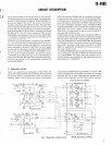
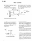
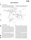
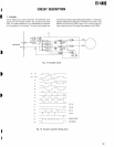
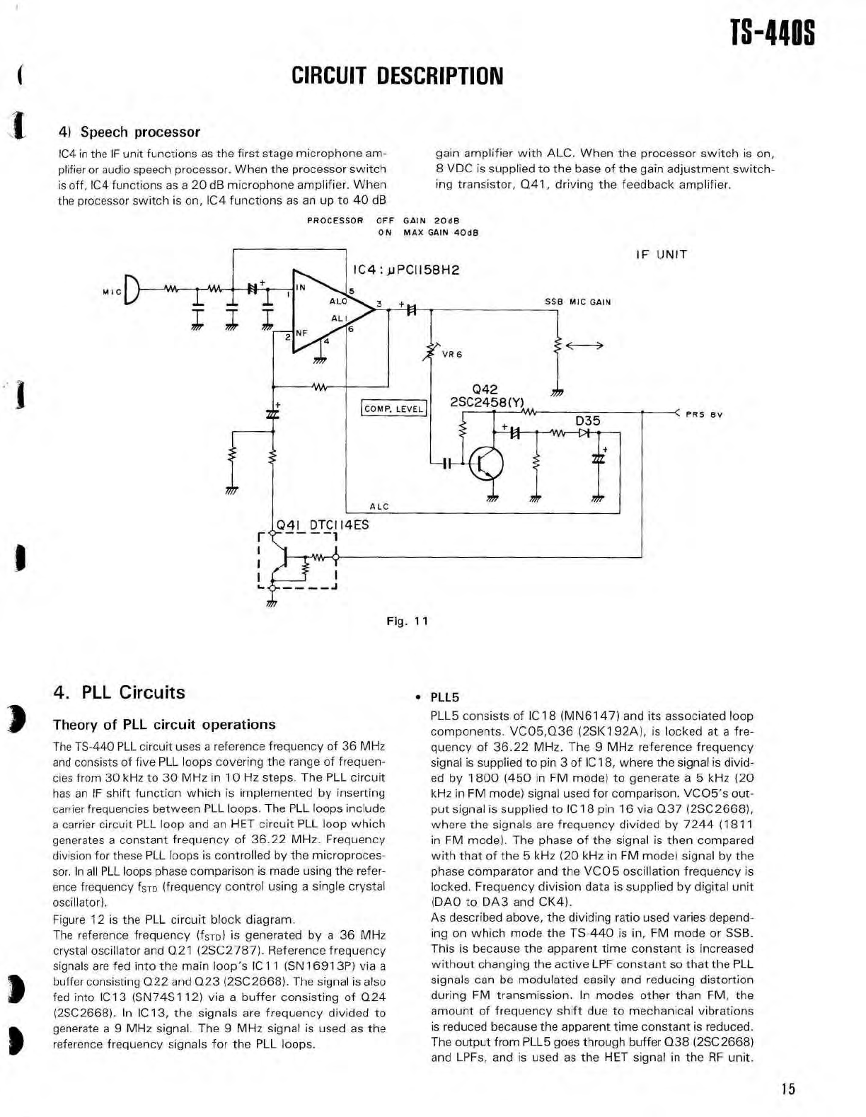
4) Speech
processo
r
IC4 in the IF unit functions as the first stage microphone am
-
plifier or audio speech processor
. When the processor switc
h
is off, IC4 functions as a 20 dB microphone amplifier
. Whe
n
the processor switch is on, IC4 functions as an up to 40 d
B
PROCESSOR OF
F
ON
Fig
. 1
1
MIC
gain amplifier with ALC. When the processor switch is on
,
8 VDC is supplied to the base of the gain adjustment switch
-
ing transistor, Q41, driving the feedback amplifier
.
GAIN 2Od
B
MAX GAIN 4Od
8
4
.
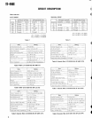
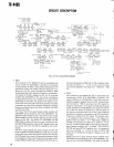
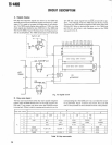
PLL Circuit
s
Theory
of
PLL
circuit
operation
s
The TS-440 PLL circuit uses a reference frequency of 36 MH
z
and consists of five PLL loops covering the range of frequen
-
cies from 30 kHz to 30 MHz in 10 Hz steps
. The PLL circui
t
has an IF shift function which is implemented by insertin
g
carrier frequencies between PLL loops
. The PLL loops includ
e
a carrier circuit PLL loop and an HET circuit PLL loop whic
h
generates a constant frequency of 36
.22 MHz
. Frequenc
y
division for these PLL loops is controlled by the microproces
-
sor
. In all PLL loops phase comparison is made using the refer
-
ence frequency fSTO (frequency control using a single crysta
l
oscillator)
.
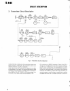
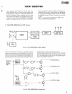
Figure 12 is the PLL circuit block diagram
.
The reference frequency (fsro) is generated by a 36 MH
z
crystal oscillator and Q21 (2SC2787)
. Reference frequenc
y
signals are fed into the main loop's IC1 1 (SN16913P) via
a
buffer consisting Q22 and Q23 (2SC2668)
. The signal is als
o
fed into IC13 (SN74S112) via a buffer consisting of Q2
4
(2SC2668)
. In IC13, the signals are frequency divided t
o
generate a 9 MHz signal
. The 9 MHz signal is used as th
e
reference frequency signals for the PLL loops
.
•
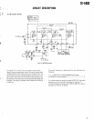
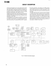
PLL
5
PLL5 consists of IC 18 (MN6147) and its associated loo
p
components
. VCO5,Q36 (2SK192A), is locked at a fre-
quency of 36
.22 MHz
. The 9 MHz reference frequenc
y
signal is supplied to pin 3 of IC 18, where the signal is divid
-
ed by 1800 (450 in FM mode) to generate
a
5 kHz (2
0
kHz in FM mode) signal used for comparison
. VCO5's out
-
put signal is supplied to IC 18 pin 16 via Q37 (2SC2668)
,
where the signals are frequency divided by 7244 (181
1
in FM mode)
. The phase of the signal is then compare
d
with that of the 5 kHz (20 kHz in FM mode) signal by th
e
phase comparator and the VCO5 oscillation frequency i
s
locked
. Frequency division data is supplied by digital uni
t
(DAO to DA3 and CK4)
.
As described above, the dividing ratio used varies depend
-
ing on which mode the TS-440 is in, FM mode or SSB
.
This is because the apparent time constant is increase
d
without changing the active LPF constant so that the PL
L
signals can be modulated easily and reducing distortio
n
during FM transmission
. In modes other than FM, th
e
amount of frequency shift due to mechanical vibration
s
is reduced because the apparent time constant is reduced
.
The output from PLL5 goes through buffer Q38 (2SC2668
)
and LPFs, and is used as the HET signal in the RF unit
.
15