


TS-440S
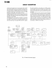
CIRCUIT DESCRIPTIO
N
FULL
BREAK-I
N
H
A
L
B
L
1
KEYING I
N
C
L
H
D
E
F
G
KEYING OU
T
L
H
L
L
L
H
H
L
CONTROL OU
T
SEMI BREAK-IN, VO
X
A
L
H
L
KEYIN
G
VOX
I
N
CONTROL OU
T
F
L
H
J
KEYING OU
T
VO
X
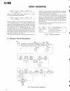
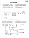
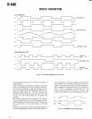
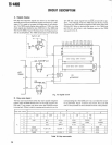
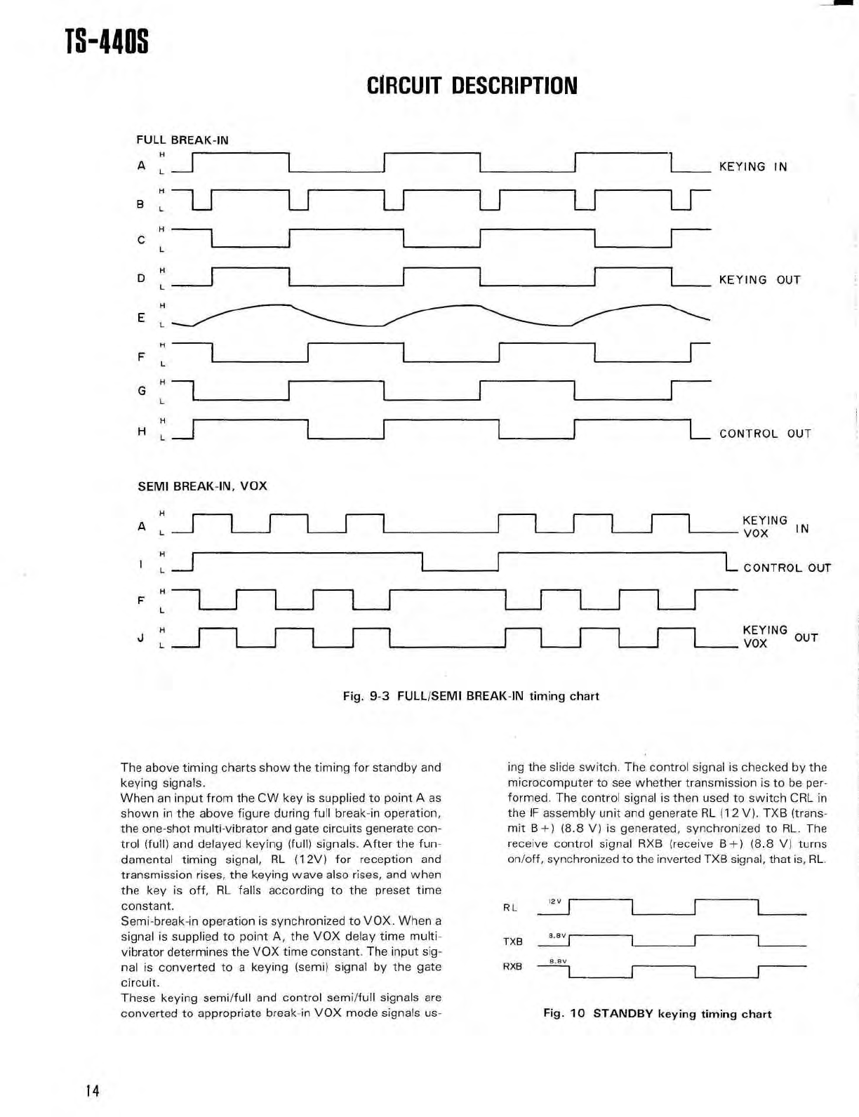
Fig
. 9-3 FULL/SEMI BREAK-IN
timing char
t
The above timing charts show the timing for standby an
d
keying signals
.
When an input from the CW key is supplied to point A a
s
shown in the above figure during full break-in operation
,
the one-shot multi-vibrator and gate circuits generate con
-
trol (full) and delayed keying (full) signals
. After the fun-
damental timing signal, RL (12V) for reception an
d
transmission rises, the keying wave also rises, and whe
n
the key is off, RL falls according to the preset tim
e
constant
.
Semi-break-in operation is synchronized to VOX
. When
a
signal is supplied to point A, the VOX delay time multi
-
vibrator determines the VOX time constant
. The input sig-
nal is converted to a keying (semi) signal by the gat
e
circuit
.
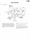
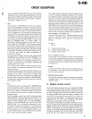
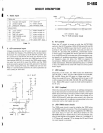
These keying semi/full and control semi/full signals ar
e
converted to appropriate break-in VOX mode signals us
-
ing the slide switch
. The control signal is checked by th
e
microcomputer to see whether transmission is to be per
-
formed
. The control signal is then used to switch CRL i
n
the IF assembly unit and generate RL (12 V)
. TXB (trans-
mit
B+)
(8
.8 V) is generated, synchronized to RL
. Th
e
receive control signal RXB (receive
B+)
(8
.8 V) turn
s
on/off, synchronized to the inverted TXB signal, that is, RL
.
RL
12
V
TXB
8
.8
v
RXB
8
.e
v
Fig
. 10 STANDBY keying timing char
t
14