


TS-440
S
CIRCUIT DESCRIPTIO
N
t
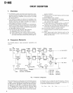
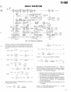
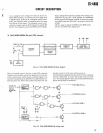
Signals from the ANT pin are fed into the RAT pin of the R
F
unit via the transmit/receive switching relay
. The signals the
n
go to the 10 BPFs through the approx
. 20 dB attenuator cir
-
cuit, the first stage of the first IF trap circuit, and the lo
w
pass filters (which pass only 500 kHz or less)
. The signal the
n
goes through the second stage of the first IF trap circuit, an
d
is mixed with the VCO signal and converted into the first I
F
signal of 45
.05 MHz in the first mixer, consisting of Q3 an
d
Q4 (2SK125-5)
. The VCO circuit consists of Q21 to Q2
4
(2SC2668Y) and oscillates in four bands from 45
.05 MH
z
to 75
.05 MHz
. Oscillator frequencies are controlled by D
C
signals from the PLL unit
.
The first IF signal of 45
.05 MHz is passed through the MC
F
(F1), which is used in both receive and transmit, and is am
-
plified by the first IF amplifier Q5 (3SK74L)
. In the secon
d
mixer, consisting of Q6 and Q7 (2SK1 25), the first IF signa
l
is mixed with the heterodyne oscillator signal (36
.22 MHz
)
from the PLL circuit, amplified by Q12 (2SC2668Y) to ob-
tain the second IF signal (8
.83 MHz)
. The second IF signa
l
of 8
.83 MHz goes through the gate of the noise blanker
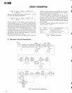
. I
n
modes other than FM , the signal then goes through the MC
F
(F2) and is fed into the IF unit through buffer amplifiers Q
8
and Q9 (2SC2668Y)
.
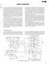
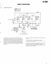
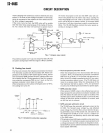
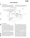
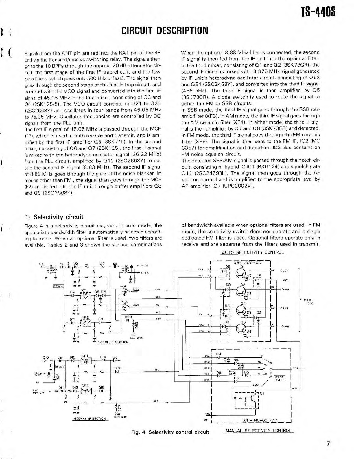
1) Selectivity circui
t
Figure 4 is a selectivity circuit diagram
. In auto mode, th
e
appropriate bandwidth filter is automatically selected accord
-
ing to mode
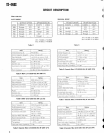
. When an optional filter is used, two filters ar
e
available
. Tables 2 and 3 shows the various combinations
When the optional 8
.83 MHz filter is connected, the secon
d
IF signal is then fed from the IF unit into the optional filter
.
In the third mixer, consisting of Q1 and Q2 (3SK73GR), th
e
second IF signal is mixed with 8
.375 MHz signal generate
d
by IF unit's heterodyne oscillator circuit, consisting of Q5
3
and Q54 (2SC2458Y), and converted into the third IF signa
l
(455 kHz)
. The third IF signal is then amplified by Q
5
(3SK73GR)
. A diode switch is used to route the signal t
o
either the FM or SSB circuits
.
In SSB mode, the third IF signal goes through the SSB cer-
amic filter (XF3)
. In AM mode, the third IF signal goes throug
h
the AM ceramic filter (XF4)
. In either mode, the third IF sig-
nal is then amplified by Q7 and Q8 (3SK73GR) and detected
.
In FM mode, the third IF signal goes through the FM cerami
c
filter (XF5)
. The signal is then sent to the FM IF, IC2 (M
C
3357) for amplification and detection
. IC2 also contains a
n
FM noise squelch circuit
.
The detected SSB/AM signal is passed through the notch cir
-
cuit, consisting of hybrid IC IC1 (BX6124) and squelch gat
e
Q12 (2SC2459BL)
. The signal then goes through the A
F
volume control and is amplified to the appropriate level b
y
AF amplifier IC7 (UPC2002V)
.
of bandwidth available when optional filters are used
. In F
M
mode, the selectivity switch does not operate and a singl
e
dedicated FM filter is used
. Optional filters operate only i
n
receive and are separate from the filters used in transmit
.
AUTO SELECTIVITY CONTROL
I
—
X59—1070—00
1
D6
01
I
558
21
,
i
l
a
< ss
R
455 3t_
.
14
/a
D
I
+
R
+
z
'
.
,$W
I
AI
AL
T
D5
02
L a
J
r
p1
<
I
cw
R
R4~~
fro
m
04
IC 1
0
D4
RY
R
D
2
~•
14
i
D3
0 3
Bew
sj
r
l
a
—
i
L_
.
j
J
<A M
R
45A
6
L
RX
B
45A
I
DI I
la
Bow
I
o
D
9
M 2
I4
N
-
88
5
455
0
D
5
45S
(
-
a
D8
6
SELEC-
TIVIT
Y
BBC
AUTO
n
AU
T
454
GNDI
F/14
—
J
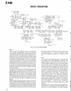
Fig
.
4
Selectivity control circuit
MANUAL SELECTIVITY CONTROL
7