


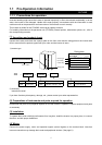
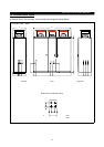

2.2 Wiring
INSTALLATION AND WIRING
5
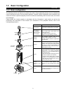
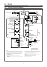
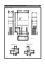
2.2.1 Terminal connection diagram
Control circuit input terminal
Main circuit terminal
Control circuit output terminal
3-phase AC power supply
24VDC power output and extemal transistor common
(Contact input common for source logic)
Reverse rotation start
Forward rotation start
Jumper
NFB MC
High
Start self-holding
selection
Multi-speed
selection
(Max. 15 speeds)
Middle
Low
Jog mode
Second acceleration/
deceleration time selection
Output stop
Reset
Current input selection
10E(+10V)
CS
AU
MRS
RES
RT
RL
JOG
RM
RH
STR
STF
PC
S1
T
R1
S
R
W
V
U
10(+5V)
2(
Selected)
4(DC 4 20mA)
Control input signals(no voltage input allowed)
Frequency setting
potentiometer
1/2W1k
Common
Auxiliary input
Current input
Inverter
FR-A500L
STOP
(Note 6)
(Note 8)
(Note 1)
(Note 4)
(Note 7)
(Note 8)
(Note 1)
(Note 9)
(Note 6)
(Note 1)
(Note 2)
Frequency setting signals (analog)
Ground
Ground
(+)
+
-
(-)
AM
Analog signal output
(DC0 10V)
Frequency detection
Instantaneous power failure
Open collector
outputs
Overload
Up to frequency
Running
Open collector output common
Common to sink and source
Moving-coil type
1mA full-scale
DC0 5V
DC0 10V
5(Analog common)
SD( )
Contact imput
common
10( Selected)
DC0 5V
DC0 10V
PU
connector
(RS-485)
IM
( )
(
)
SD
FM
RUN
A
B
C
SU
OL
IPF
FU
SE
Meter
(e.q.frequency meter)
calibration resistor
1/2W10k
Error output
(contact output)
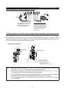
(1) This connection diagram shows the example for the sink logic (factory-
set) control circuit. When using the source logic, refer to page 14 for the
connections.
(2) Use of the 2W1k is recommended when the frequency setting is
changed frequently.
(3) Always connect the enclosed DCL at P1, P. (375,450K)
DCL is prewired in the panel. P1 terminal is not prepared as terminals.
(530-900K)
(4) The output terminal can output the error alarm code, and 26 types of
functions can be independently assigned with Pr. 190 to 195.
(5) The input signal can be changed over with Pr.73.
(6) This is not required when the scale is calibrated with the operation
panel.
(7) Always ground the inverter unit, DCL and motor.
(8) JOG is assigned. (375-900K)
Notes
Selection of automatic restart
after instantaneous power
failure
Motor
+
-
+
-
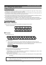
Brake unit
option
530K-900K
P(+)
P
P
N
P
PR
72
+
E
DCL
P1
Brake
resistor
(option)
PR
+
P
DCL
375K, 450K 530K-900K
N
Built in
Option
(External Option)
Brake
Resistor
(See Page 49)