


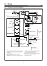

INSTALLATION AND WIRING
13
(
3
)
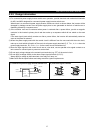
Changing the control logic
The input signals are set to sink logic for the NA version, and to source logic for the EC version.
To change the control logic, the connector on the back of the control circuit terminal block must be moved to
the other position.
(The output signals may be used in either the sink or source logic independently of the connector position.)
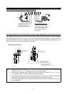
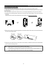
1) Loosen the two mounting screws in both ends of the control circuit terminal block. (The screws cannot be
removed.)
With both hands, pull down the terminal block from the back of the control circuit terminals.
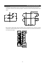
2) Remove the connector in the sink logic position on the back surface of the control circuit terminal block and
fit it to the source logic position.
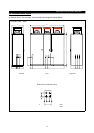
SINK
CON3
CON2
SOURCE
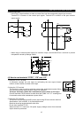
SINK
CON3
CON2
SOURCE
NA version
SINK
CON3
CON2
EC version
SOURCE
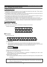
3) Using care not to bend the pins of the control circuit connector, reinstall the control circuit terminal block
and fix it with the mounting screws.
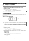
Note: 1. Make sure that the control circuit connector is fitted correctly.
2. While power is on, never disconnect the control circuit terminal block.
3. The sink-source logic change-over connector must be fitted in only one of those positions. If it is
fitted in both positions at the same time, the inverter may be damaged.