


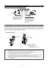

INSTALLATION AND WIRING
7
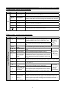
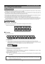
Type Symbol Terminal Name Description
10E
10VDC, permissible load current
10mA
10
Frequency setting
power supply
5VDC, permissible load current
10mA
When the frequency setting potentiometer is
connected in the factory-set state, connect it to
terminal 10.
When it is connected to terminal 10E, change the
input specifications of terminal 2.
2
Frequency setting
(voltage)
By entering 0 to 5VDC (0 to 10VDC), the maximum output frequency is reached at 5V
(or 10V) and I/O are proportional. Switch between input 0 to 5VDC (factory setting)
and 0 to 10VDC from operation terminal. Input resistance 10k
Ω
. Maximum
permissible voltage 20V.
4
Frequency setting
(current)
By entering 4 to 20mADC, the maximum output frequency is reached at 20mA and I/O
are proportional. This input signal is valid only when the AU signal
is on. Input
resistance 250
Ω
. Maximum permissible current 30mA.
1
Auxiliary frequency
setting
By entering 0 to
±
5VDC 0 to
±
10VDC, this signal is added to the frequency setting
signal of terminal 2 or 4. Switch between input 0 to
±
5VDC and 0 to
±
10VDC (factory
setting) from operation terminal. Input resistance 10k
Ω
. Maximum permissible voltage
±
20V.
Input signals
Analog frequency setting
5
Frequency setting
input common
Common to the frequency setting signal (terminal 2, 1 or 4) and analog output terminal
AM. Do not earth.
Contact
A B C Alarm output
Change-over contact output indicating that the output has been
stopped by the inverter protective function activated.
200VAC 0.3A, 30VDC 0.3A. Alarm: discontinuity across B-C
(continuity across A-C), normal: continuity across B-C
(discontinuity across A-C).
RUN Inverter running
Switched low when the inverter output frequency is equal to or
higher than the starting frequency (factory set to 0.5Hz, variable).
Switched high during stop or DC dynamic brake operation
(note1)
Permissible load 24VDC 0.1A.
SU Up to frequency
Switched low when the output frequency has reached within
±
10%
of the set frequency (factory setting, variable). Switched high
during acceleration, deceleration or stop
(note 1)
. Permissible load
24VDC 0.1A.
OL Overload alarm
Switched low when the stall prevention function has caused stall
prevention to be activated. Switched high when stall prevention is
reset
(note 1)
. Permissible load 24VDC 0.1A.
IPF
Instantaneous power
failure
Switched low when instantaneous power failure or undervoltage
protection is activated
(note 1)
. Permissible load 24VDC 0.1A.
FU Frequency detection
Switched low when the output frequency has reached or exceeded
the detection frequency set as appropriate. Switched high when
below the detection frequency
(note 1)
. Permissible load 24VDC
0.1A
Output terminal
function selection
(Pr. 190 to Pr.
195) change
terminal functions.
Open collector
SE
Open collector output
common
Common to the RUN, SU, OL, IPF and FU terminals.
Pulse
FM For meter
Factory setting of output item:
Frequency
Permissible load current 1mA
1440 pulses/second. at 60Hz
Output signals
Analog
AM Analog signal output
One selected from 16 monitoring
items, such as output frequency,
is output
(note 2)
.
The output signal is proportional
to the magnitude of each
monitoring item.
Factory setting of output item:
Frequency
Output signal 0 to 10VDC
Permissible load current 1mA
Communication
RS485
PU connector
With the operation panel connector, communication can be made through RS-485.
∙
Conforming Standard : EIA Standard RS-485
∙
Transmission format : Multi-drop link
∙
Communication speed: Maximum 19200 baud rates
∙
Overall length : 500m
Note1: Low indicates that the open collector outputting transistor is on (conducts). High indicates that the
transistor is off (does not conduct).
Note2: Not output while the inverter is reset.