


Appendix 4
APPENDICES
49
Appendix 4
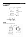
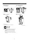
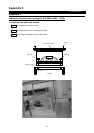
Installation procedure for brake unit (option) (FR-A540L-530K 800K)
Step1
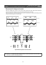
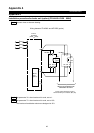
Connect wires as the next drawing.
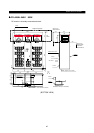
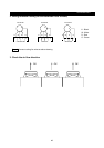
Wiring between FR-A500L and MT-BR5 (option)
P
Inverter
FR-A500L
800K)
(530K
P
MT-BR5
P
TH1
TH2
PR
PR
E
P
MT-BR5
P
TH1
TH2
PR
PR
E
Brake
Unit
(Option)
PR
N
RESISTOR TEMPERATURE
ABNORMAL SIGNALS
These signals should be used at
Abnormal for input contactor (MC) trip.
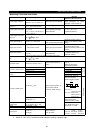
Step2
Set parameter 30 : when brake unit is used, set to 1.
Step3
Set parameter 70 : when brake unit is used, set to 10%.
This brake unit and brake resistor are designed at 10%.