


SPECIFICATION
S
46
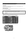
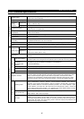
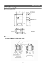
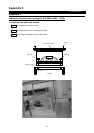
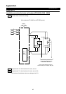
Panel cut diagram Panel cut diagram
Parameter unit(option)
FR-PU04
Operation panel
FR-DU04
72(2.83)
15
(0.59)
9.7
(0.38)
16.5(0.65)
24(0.94)
46.5(1.83)
81.5(3.21)
20(0.79)
2- 4hole
54(2.13)
16.5
(0.65)
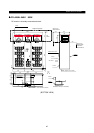
72(2.83)
15
(0.59)
80(3.15) 21.5(0.85)
45
(1.77)
24
(0.94)
13(0.51)
20
(0.79)
13
(0.51)
18.5
(0.73)
40(1.57)
16.5(0.65)
9.7
(0.38)
125(4.92)
23.75(0.94)
17(0.67)
19.75(0.78)
3.5(0.14)
46.5(1.83)
3.25(0.13)
54(2.13)
43.75(1.72)
17(0.67)
81.5(3.21)
11.75(0.46)
1.5(0.06)
1.25(0.05)
13
(0.51)
1.5(0.06)
40(1.57)3.75(0.14)
(Unit : mm(inches))
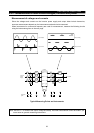
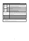
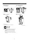
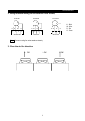
PU connector pin layout
(Looking from front of inverter unit "receptacle side")
Note) 1. Do not connect to the computer’s LAN board, FAX modem
socket or telephone modular connector. The electrical
specifications differ, so the product could be damaged if
connected.
2. The No.2 and 8 pins (P5S) are the power supply for the
parameter unit. Do not use these when carrying out RS-485
communication.
5- 4hole
5- 4hole
2- 4hole
SG
P5S
RDA
SDB
SDA
RDB
SG
P5S
1
2
3
4
1
2
5
6
7
8