


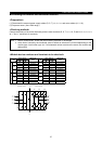
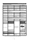
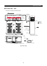
6.1 Standard specification
SPECIFICATION
S
41
6.1.1 Model specifications
(Note 8) (Note 8)
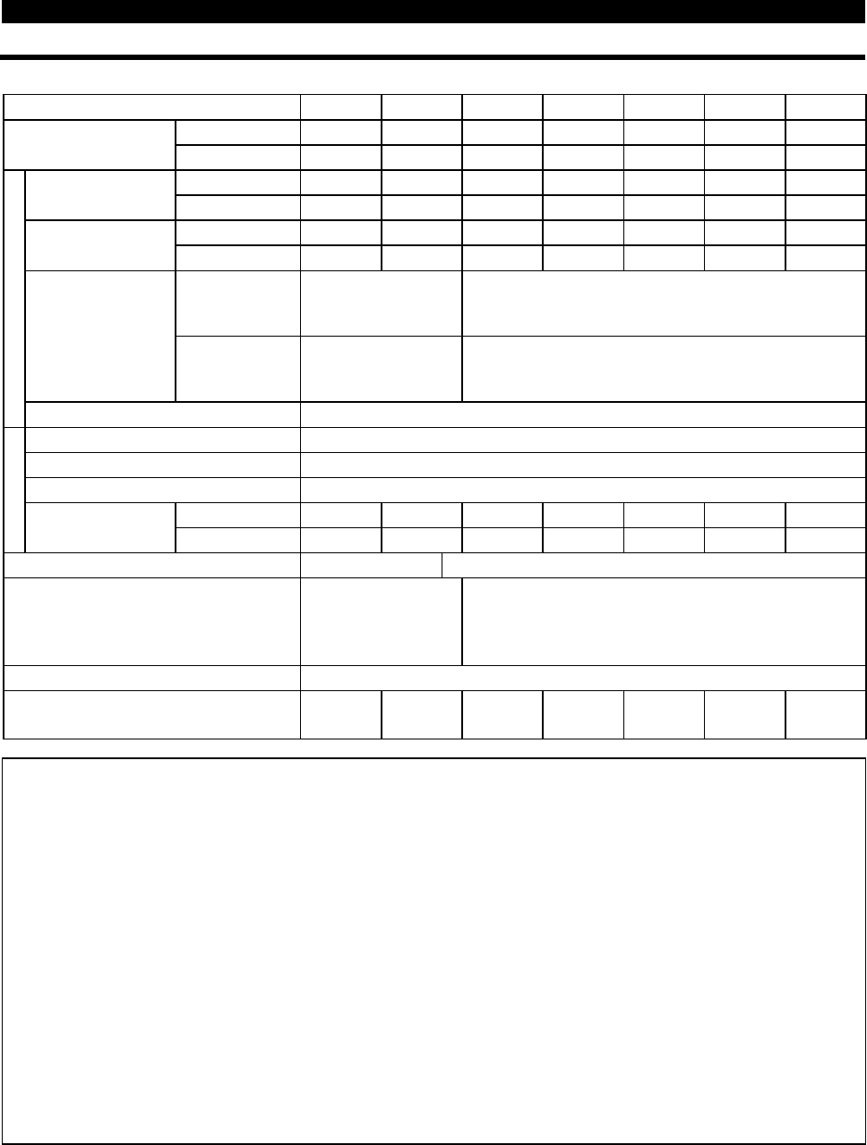
Model FR-A540L-
K-NA
375 450 530 600 670 750 800
Constant torque 375 450 530 600 670 750 800
Applicable motor
capacity (kW)
(Note 1)
Variable torque 450 530 600 670 750 800 900
Constant torque 600 700 800 900 1000 1150 1250
Rated capacity (HP)
(Note 2)
Variable torque 700 800 900 1000 1150 1250 1400
Constant torque 722 866 1010 1152 1296 1440 1584
Rated current (A)
Variable torque 866 1010 1152 1296 1440 1534 1728
Constant torque
150% 60 sec., 200%
0.5 sec. (inverse-time
characteristics)
150% 60 sec. (inverse-time characteristics)
Overload capacity
Variable torque
120% 60 sec., 150%
0.5 sec. (inverse-time
characteristics)
120% 60 sec. (inverse-time characteristics)
Output
Voltage Three phase, 380-480V 50 60Hz
Rated input AC voltage, frequency
Three phase, 380-480V 50 60Hz
Tolerable AC voltage fluctuation
323-528V 50 60Hz
Tolerable frequency fluctuation
5%
Constant torque 550 660 770 878 988 1097 1210
Power supply
Power facility
capacity (kVA)
Variable torque 660 770 878 988 1097 1210 1320
Protective structure (JEM 1030) Open type (IP00) Open type (IP20)
Ambient temperature
-10
°
C to 40
°
C
(14
°
F to 104
°
F) at VT
-10
°
C to 50
°
C
(14
°
F to 122
°
F) at CT
-10
°
C to 40
°
C (14
°
F to 104
°
F)
Cooling method
Forced air cooling
Approx. weight (kg (lb) )
490
(1078)
500
(1100)
1060
(2332)
1060
(2332)
1100
(2420)
1100
(2420)
1200
(2640)
Note: 1. The applicable motor capacity indicated is the maximum capacity applicable when Mitsubishi 4-
pole standard motor is used For A540K.
2. The rated output capacity indicated is based on for A540L.
3. The overload capacity indicated in % is the ratio of the overload current to the inverter’s rated
current. For repeated duty, allow time for the inverter and motor to return to or below the
temperatures under 100% load.
4. The maximum output voltage cannot exceed the power supply voltage. The maximum output
voltage may be set as desired below the power supply voltage.
5. The power supply capacity changes with the values of the power supply side inverter impedance
(including those of the input reactor and cables).
6. For use in Variable torque mode, refer to Pr. 570.
7. For inverter environmental conditions (including ambient temperature) please check page A-3.
8. Preliminary ratings.