


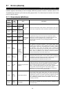

5.2 Troubleshooting
PROTECTIVE FUNCTIONS
30
If any function of the inverter is lost due to occurrence of a fault, clear up the cause and make correction in
accordance with the following procedure. Contact your sales representative if the corresponding fault is not
found below, the inverter has failed, parts have been damaged, or any other fault has occurred.
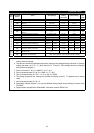
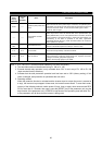
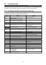
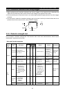
5.2.1 Checking the operation panel display at alarm stop
The alarm code is displayed on the operation panel to indicate the cause of a faulty operation. Clear up the
cause and take proper action in accordance with the following table:
Operation Panel
Display
Check Point Remedy
E.OC1
Acceleration too fast?
Check for output short circuit or ground fault.
Increase acceleration time.
E.OC2
Sudden load change?
Check for output short circuit or ground fault.
Keep load stable.
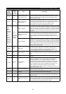
E.OC3
Deceleration too fast?
Check for output short circuit or ground fault.
Mechanical brake of motor operating too fast?
Increase deceleration time.
Check brake operation.
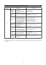
E.OV1 Acceleration too fast? Increase acceleration time.
E.OV2 Sudden load change? Keep load stable.
E.OV3 Deceleration too fast?
Increase deceleration time. (Set deceleration time
which matches load GD
2
.)
Reduce braking duty.
E.THM
E.THT
Motor used under overload?
Reduce load.
Increase motor and inverter capacities.
E.IPF Check the cause of instantaneous power failure. Restore power.
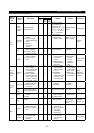
E.UVT
Large-capacity motor started?
Jumper or DC reactor connected across terminals P-
P1?
Check power system equipment such as power
supply.
Connect jumper or DC reactor across terminals P-P1.
E.FIN Ambient temperature too high? Set ambient temperature within specifications.
E. GF Check motor and cables for ground fault. Resolve ground faults.
E.OHT Check motor for overheat. Reduce load and frequency of operation.
E.OLT Motor used under overload?
Reduce load.
Increase motor and inverter capacities.
E.OPT Check for loose connectors. Connect securely
E.OP1 to E.OP3
Option function setting or operation proper?
(1 to 3 indicate the option slot numbers.)
Check the option function setting, etc.
E. PE Number of parameter write times too many? Control card
E.PUE DU or PU fitted securely? Fit DU or PU securely.
E.RET Check cause of alarm.
E.LF Check for open output phase. Repair open phase.
E.CPU Check for loose connectors.
Change inverter.
Connect securely.
E.P24 Check PC terminal output for short. Repair short.
E.CTE Check PU connector cable for short. Check PU and cable.
E.MB1 to MB7 Check brake sequence.
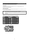
PS
STOP key of operation panel pressed during external
operation to stop?
Check load status.
Refer to Pr.75.
RB Brake resistor used too often? Increase deceleration time.
TH Load too large? Sudden acceleration? Reduce load amount or frequency of running.
OL
Motor used under overload?
Sudden deceleration?
oL: Overvoltage stall
OL: Overcurrent stall
Lighten load.
Reduce frequency of braking.
E.14(DC fuse) Is the DC circuit short circuited?
Repair the short-circuited section, and replace the DC
fuse.