


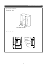

INSTALLATION AND WIRING
12
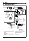
2.2.3 Wiring of the control circuit
(
1
)
Wiring instructions
1) Terminals SD, SE and 5 are common to the I/O signals and isolated from each other. These common
terminals must not be connected to each other or earthed.
2) Use shielded or twisted cables for connection to the control circuit terminals and run them away from the
main and power circuits (including the 200V relay sequence circuit).
3) The frequency input signals to the control circuit are micro currents. When contacts are required, use two or
more parallel micro signal contacts or a twin contact to prevent a contact fault.
4) It is recommended to use the cables of 0.75mm
2
gauge for connection to the control circuit terminals.
If the cable gauge used is 1.25mm
2
or more, the front cover may be lifted when there are many cables
running or the cables are run improperly, resulting in an operation panel or parameter unit contact fault.
(
2
)
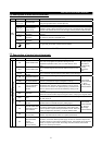
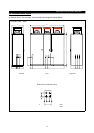
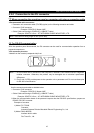
Terminal block layout
z
zz
z
NA version OR Version
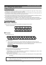
In the control circuit of the inverter, the terminals are arranged as shown below:
Terminal screw size: M3.5
A
RL
SE RUN SU IPF OL FU SD STF STR JOG CS
RM RH RT AU STOP MRS RES SD FM
B C PC AM 10E 10 2 5 4 1
z
zz
z
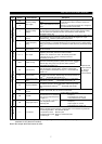
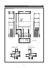
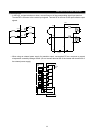
EC version
Terminal screw size : M3
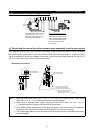
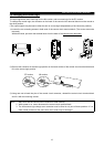
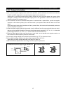
<Wiring procedure>
1) For the wiring of the control circuit, strip the sheaths of the cables and use them as they are.
Strip the sheath to the following dimension. If too much is stripped this may cause a short circuit with
the neighboring cable. If too little stripped this may cause cable disconnection.
6mm
±
1mm
2) Loosen the terminal screw and insert the cable into the terminal.
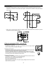
3) Tighten the screw to the specified torque.
Undertigthening can cause cable disconnection or malfunction. Overtightening can cause a short
circuit or malfunction due to the screw or unit damaged.
Tightening torque : 5 to 6 kgf cm
Note : Wire the stripped cable by twisting it to prevent it from becoming loose. (Do not plate the cable
with solder.)
Note : 1. Use a NFB (No fuse breakers) or fuse on the inverter input (primary) side.
2. Make sure that the control circuit terminal wiring does not touch power circuit terminals (or
screws) or conducting power circuit.
SE RUN SU LPF OL FU STOP MRS RES PC STF STR JOG CS FM SD
A B C SD AM 10E 10 2 5 4 1 RL RM RH RT AU