


SPECIFICATION
S
42
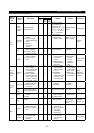
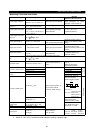
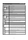
6.1.2 Common specifications
Control system
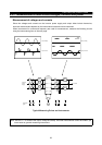
Soft-PWM control/high carrier frequency PWM control (V/F control or advanced magnetic flux
vector control can be selected)
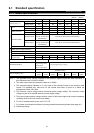
Output frequency range 0.2 to 400Hz
Analog input
0.015Hz/60Hz (terminal 2 input: 12 bits/0 to 10V, 11 bits/0 to 5V, terminal 1 input: 12 bits/
−
10 to
+10V, 11 bits/
−
5 to +5V)
Frequency
setting
resolution
Digital input 0.01Hz
Frequency accuracy
Within
±
0.2% of maximum output frequency (25
°
C
±
10
°
C ) for analog input, within 0.01% of set
output frequency for digital input
Voltage/frequency
characteristic
Base frequency set as required between 0 and 400Hz. Constant torque or variable torque
pattern can be selected.
Starting torque 150%: At 0.5Hz (for advanced magnetic flux vector control)
Torque boost Manual torque boost
Acceleration/deceleration
time setting
0 to 3600 sec (acceleration and deceleration can be set individually), linear or S-pattern
acceleration/deceleration mode can be selected.
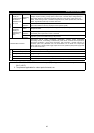
DC dynamic brake Operation frequency (0 to 120Hz), operation time (0 to 10 sec), voltage (0 to 30%) variable
Control specifications
Stall prevention operation
level
Operation current level can be set (0 to 150% variable), presence or absence can be selected.
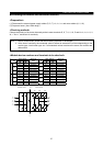
Analog input 0 to 5VDC, 0 to 10VDC, 0 to
±
10VDC, 4 to 20mADC
Frequency
setting signal
Digital input
3-digit BCD or 12-bit binary using operation panel or parameter unit
(when the FR-A5AX option is used)
Start signal
Forward and reverse rotation, start signal automatic self-holding input (3-wire input) can be
selected.
Multi-speed selection
Up to 15 speeds can be selected. (Each speed can be selected in the range of 0 to 400Hz. The
operation speed can be changed from the operation panel or parameter unit during operation.)
Second, third
acceleration/
deceleration time
selection
0 to 3600 sec (up to three different accelerations and decelerations
can be set individually.)
Current input selection Input of frequency setting signal 4 to 20mADC (terminal 4) is selected.
Output stop Instantaneous shut-off of inverter output (frequency, voltage)
Input signals
Alarm reset Alarm retained at the activation of protective function is reset.
Operation functions
Maximum/minimum frequency setting, frequency jump operation, external thermal relay input
selection, polarity reversible operation, automatic restart operation after instantaneous power
failure, commercial power supply-inverter switch-over operation, forward/reverse rotation
prevention, slip compensation, operation mode selection, offline auto tuning function, online
auto tuning function, PID control, programmed operation, computer link operation (RS-485)
Operating status
5 different signals can be selected from inverter running, up to frequency, instantaneous power
failure (undervoltage), frequency detection, second frequency detection, third frequency
detection, during program mode operation, during PU operation, overload alarm, regenerative
brake pre-alarm, electronic overcurrent protection pre-alarm, zero current detection, output
current detection, PID lower limit, PID upper limit, PID forward/reverse rotation, commercial
power supply-inverter switch-over MC1, 2, 3, operation ready, brake release request, fan fault
and fin overheat pre-alarm minor fault. Open collector output.
Alarm (inverter trip)
Contact output...change-over contact (230VAC 0.3A, 30VDC 0.3A)
Open collector...alarm code (4 bit) output
Operational specifications
Output signals
For meter
1 signal can be selected from output frequency, motor current (steady or peak value), output
voltage, frequency setting, running speed, motor torque, converter output voltage (steady or
peak value), regenerative brake duty, electronic overcurrent protection load factor, input power,
output power, load meter, and motor exciting current. Pulse train output (1440 pulses/sec./full
scale) and analog output (0 to 10VDC).