


INSTALLATION AND WIRING
6
(
1
)
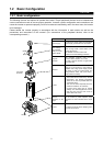
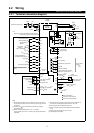
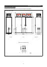
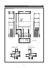
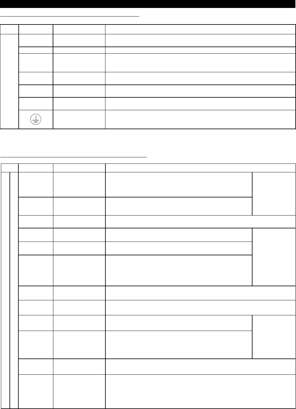
Description of main circuit terminals
Type
Symbol Terminal Name Description
R, S, T
<L
1
, L
2
, L
3
>
AC power input
Connect to the commercial power supply. Keep these terminals unconnected when
using the high power factor converter (MT-HC).
U, V, W Inverter output Connect a three-phase squirrel-cage motor.
R1, S1
<L
11
, L
21
>
Power supply for
control circuit
Connected to the AC power supply terminals R and S. To retain the alarm display
and alarm output or when using the high power factor converter (MT-HC), remove the
jumpers from terminals R-R1 and S-S1 and apply external power to these terminals.
P, N
<+,->
Optional converter
connection
Connect the optional power return converter (MT-RC) or high power factor converter
(MT-HC).
P, P1
DC reactor
connection
Connect the enclosed DC reactor. (375, 450K)
DC reactor is prewired in 530-800K sizes.
P, PR
<+, PR>
Brake resistor
connection
Connect the optional FR-BR5 brake resistor.
Main
circuit
Ground For grounding the inverter chassis. Must be earthed.
Note:< >Terminal names in parentheses are those of the EC version.
(
2
)
Description of control circuit terminals
Type Symbol Terminal Name Description
STF Forward rotation start
Turn on the STF signal to start forward rotation and turn it off to
stop. Acts as a programmed operation start signal in the
programmed operation mode. (Turn on to start and turn off to
stop.)
STR Reverse rotation start
Turn on the STR signal to start reverse rotation and turn it off to
stop.
When the STF
and STR signals
are turned on
simultaneously,
the stop
command is
given.
STOP
Start self-holding
selection
Turn on the STOP signal to select the self-holding of the start signal.
RH RM RL Multi-speed selection
Use the RH, RM and RL signals as appropriate to select multiple
speeds.
(JOG) JOG mode selection
This terminal connected internally, can not be used by the
customer. (530-800K:this signal is assigned in Factory.)
RT
Second acceleration/
deceleration time
selection
Turn on the RT signal to select the second acceleration/
deceleration time. When the second functions such as "second
torque boost" and "second V/F (base frequency)" functions have
been set, these functions can also be selected by turning on the
RT signal.
Input terminal
function selection
(Pr. 180 to
Pr. 186) change
terminal functions.
MRS Output stop
Turn on the MRS signal (20ms or longer) to stop the inverter output.
Used to shut off the inverter output to bring the motor to a stop by the magnetic brake.
RES Reset
Used to reset the protective circuit activated. Turn on the RES signal for more than 0.1
sec, then turn it off.
AU
Current input
selection
Only when the AU signal is turned on, the inverter can be
operated with the 4-20mADC frequency setting signal.
CS
Automatic restart after
instantaneous power
failure selection
With the CS signal on, restart can be made automatically when
the power is restored after an instantaneous power failure. Note
that this operation requires restart parameters to be set. When the
inverter is shipped from the factory, it is set to disallow restart.
Input terminal
function selection
(Pr. 180 to Pr.
186) change
terminal functions.
SD
Contact input
common (sink)
Common terminal for the terminal FM.
Common output terminal for 24VDC 0.1A power (PC terminal).
Input signals
Contacts, e.g. start, function setting
PC
24VDC power and
external transistor
common
Contact input
common (source)
When transistor output (open collector output), such as a programmable controller, is
connected, connect the external power supply common for transistor output to this
terminal to prevent a fault caused by leakage current. This terminal can be used as a
24VDC, 0.1A power output. When source logic has been selected, this terminal
serves as a contact input common.