


5.1 Errors (Alarms)
PROTECTIVE FUNCTIONS
24
If any fault has occurred in the inverter, the corresponding protective function is activated and the error (alarm)
indication appears automatically on the PU display. When the protective function is activated, refer to "5.2
Troubleshooting" and clear up the cause by taking proper action. If an alarm stop has occurred, the inverter
must be reset to restart it.
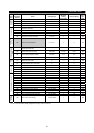
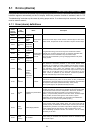
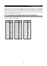
5.1.1 Error (alarm) definitions
Operation
Panel
Displa
y
(
FR-DU04
)
Parameter
Unit
(FR-PU04)
Name Description
E.OC1
OC During
Acc
During
acceleration
E.OC2
Stedy Spd
OC
During
constant
speed
E.OC3
OC During
Dec
During
deceleration
During stop
Overcurrent
shut-off
When the inverter output current reaches or exceeds approx. 200% of the
rated current, the protective circuit is activated to stop the inverter output.
E.OV1
OV During
Acc
During
acceleration
E.OV2
Stedy Spd
OV
During
constant
speed
E.OV3
OV During
Dec
During
deceleration
During stop
Regenerative
overvoltage
shut-off
If regenerative energy from the running motor causes the inverter's
internal main circuit DC voltage to reach or exceed the specified value,
the protective circuit is activated to stop the inverter output.
This may also be activated by a surge voltage generated in the power
supply system.
E.THM
Motor
Ovrload
Motor
The electronic overcurrent protection in the inverter detects motor
overheat due to overload or cooling capability reduced during constant-
speed operation. When 85% of the preset value is reached, pre-alarm
(TH indication) occurs. When the specified value is reached, the
protective circuit is activated to stop the inverter output. When a special
motor such as a multi-pole motor or more than one motor is run, the
motor cannot be protected by the electronic overcurrent protection.
Provide a thermal relay in the inverter output circuit.
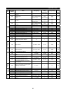
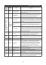
E.THT
Inv.
Overload
Overload
shut-off
(electronic
overcurrent
protection)
Inverter
If a current not less than 150% of the rated output current flows and
overcurrent shut-off (OC) does not occur (200% or less), inverse-time
characteristics cause the electronic overcurrent protection to be activated
to stop the inverter output. (Overload immunity: 150%, 60 sec)
At low-speed regions, the operation time may be short.
E.IPF
Inst.Pwr.
Loss
Instantaneous power failure
protection
If a power failure has occurred in excess of 15msec (this applies also to
inverter input shut-off), this function is activated to stop the inverter output
to prevent the control circuit from misoperation. At this time, the alarm
output contacts are opened (across B-C) and closed (across A-C).
(Note 1) If a power failure persists for more than 100ms, the alarm output
is not provided, and if the start signal is on at the time of power
restoration, the inverter will restart. (If a power failure is instantaneous
within 15msec, the control circuit operates properly.)
E.UVT
Under
Voltage
Undervoltage protection
If the inverter power supply voltage drops, the control circuit will not
operate properly. Furthermore, the motor torque could drop and the heat
generated may increase. The inverter output will be stopped if the power
supply voltage drops to 150V (approx. 300V for 400V class) or less.
The undervoltage protection function will activate if the DC reactor
accessory is not used.
E.FIN
H/Sink
O/Temp
Fin overheat
If the cooling fin overheats, the temperature sensor is activated to stop
the inverter output.