


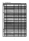
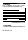

PROTECTIVE FUNCTIONS
25
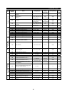
Operation
Panel
Display
(FR-DU04)
Parameter
Unit
(FR-PU04)
Name Description
E. GF
Ground
Fault
Output side ground fault
overcurrent protection
This function stops the inverter output if a ground fault occurs in the
inverter's output (load) side and a ground fault current flows. A ground
fault occurring at low ground resistance may activate the overcurrent
protection (OC1 to OC3).
E.OHT OH Fault
External thermal relay
operation (Note 3)
If the external thermal relay designed for motor overheat protection or the
internally mounted temperature relay in the motor switches on (relay
contacts "open"), the inverter output can be stopped if those contacts had
been entered into the inverter. If the relay contacts are reset
automatically, the inverter will not restart unless it is reset.
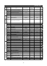
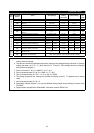
During acceleration
If a current not less than 150% (Note 4) of the rated inverter current flows
in the motor, this function lowers the frequency until the load current
reduces to prevent the inverter from resulting in overcurrent shut-off.
When the load current has reduced below 150%, this function increases
the frequency again to accelerate and operate the inverter up to the set
frequency.
During constant-speed
operation
If a current not less than 150% (Note 4) of the rated inverter current flows
in the motor, this function lowers the frequency until the load current
reduces to prevent overcurrent shut-off. When the load current has
reduced below 150%, this function increases the frequency up to the set
value.
E.OLT
(When
stall
prevention
operation
has
reduced
the
running
frequency
to 0. OL
during stall
prevention
operation)
Stll Prev
STP
(OL shown
during stall
prevention
operation)
During deceleration
If the regenerative energy of the motor has increased above the brake
capability, this function increases the frequency to prevent overvoltage
shut-off. If a current not less than 150% (Note 4) of the rated inverter
current flows in the motor, this function increases the frequency until the
load current reduces to prevent the inverter from resulting in overcurrent
shut-off. When the load current has reduced below 150%, this function
decreases the frequency again.
E.OPT
Option
Fault
Option alarm
Stops the inverter output if the dedicated inboard option used in the
inverter results in setting error or connection (connector) fault.
When the high power factor converter connection is selected, this
alarm is displayed if AC power is connected to R, S, T.
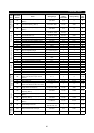
E.OP1 to
OP3
Option slot
alarm
1 to 3
Option slot alarm
Stops the inverter output if a functional fault (such as communication error
of the communication option) occurs in the inboard option loaded in any
slot.
E. PE
Corrupt
Memry
Parameter error
Stops the output if a fault occurs in E
2
PROM which stores parameter
settings.
E.PUE
PU Leave
Out
PU disconnection
occurrence
This function stops the inverter output if communication between inverter
and PU is suspended, e.g. the operation panel or parameter unit is
disconnected, when "2", "3", "16" or "17" is set in Pr. 75 "reset
selection/PU disconnection detection/PU stop selection". This function
stops the inverter output if the number of successive communication
errors is greater than the number of permissible retries when Pr. 121
value is "9999" for RS-485 communication from PU connector.
This function stops the inverter output if communication is broken for a
period of time set in Pr. 122.
E.RET
Retry No
Over
Retry count exceeded
If operation cannot be resumed within the number of retries set, this
function stops the inverter output.
E.LF
Open output phase
protection
This function stops the inverter output when any of the three phases (U,
V, W) on the inverter's output side (load side) opens.
E.CPU CPU Fault CPU error
If the arithmetic operation of the built-in CPU does not end within a
predetermined period, the inverter self-determines it has an alarm and
stops the output.
E.P24
24VDC power output short
circuit
When 24VDC power output from the PC terminal is shorted, this function
shuts off the power output. At this time, all external contact inputs switch
off. The inverter cannot be reset by entering the RES signal. To reset, use
the operation panel or switch power off, then on again.