


2004 Jan 26 11
Philips Semiconductors Product specification
MPEG-2 video and MPEG-audio/AC-3
audio encoder with multiplexer
SAA6752HS
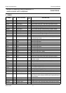
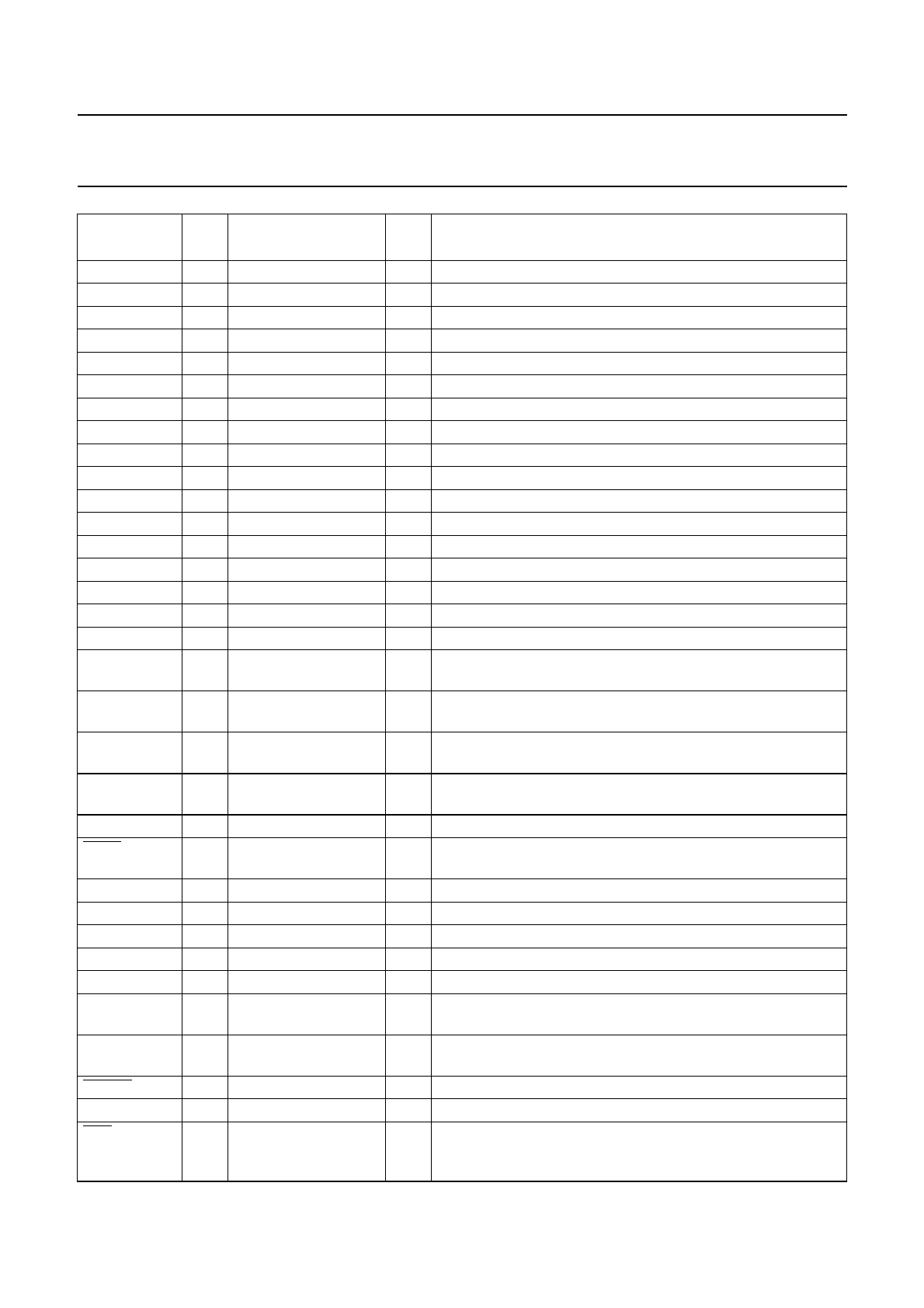
SD_DQ21 117 input/output 8 reserved (do not connect)
SD_DQ25 118 input/output 8 reserved (do not connect)
V
DDP
119 supply − pad ring supply voltage (3.3 V)
SD_DQ22 120 input/output 8 reserved (do not connect)
SD_DQ24 121 input/output 8 reserved (do not connect)
SD_DQ23 122 input/output 8 reserved (do not connect)
EXTCLK 123 input − 27 MHz external clock input with internal pull-up resistor
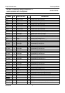
V
SSP
124 ground − pad ground
V
SSA
125 ground − oscillator analog ground
XTALI 126 analog input − crystal oscillator input (27 MHz); note 2
XTALO 127 analog output − crystal oscillator output (27 MHz)
V
DDA
128 supply − oscillator analog supply voltage (2.5 V)
V
SSCO
129 ground − core ground
V
SSCO
130 ground − core ground
V
DDCO
131 supply − core supply voltage (2.5 V)
V
DDCO
132 supply − core supply voltage (2.5 V)
V
DDP
133 supply − pad ring supply voltage (3.3 V)
TDI 134 input − boundary scan test data input; pin must float or set to HIGH
during normal operating; with internal pull-up resistor; note 3
TMS 135 input − boundary scan test mode select; pin must float or set to HIGH
during normal operating; with internal pull-up resistor; note 3
TCK 136 input − boundary scan test clock; pin must be set to LOW during
normal operating; with internal pull-up resistor; note 3
TDO 137 3-state output 4 boundary scan test data output; pin not active during normal
operating; with 3-state output; note 3
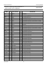
V
SSP
138 ground − pad ground
TRST 139 input − test reset input (active LOW), for boundary scan test (with
internal pull-up resistor); notes 3 and 4
CLKOUT 140 output 4 27 MHz system clock output
TEST0 141 input/output 4 reserved (do not connect)
TEST1 142 input/output 4 reserved (do not connect)
V
DDP
143 supply − pad ring supply voltage (3.3 V)
TEST2 144 input/output 4 reserved (do not connect)
SDA 145 input/open-drain
output
− I
2
C-bus serial data input/output
SCL 146 input/open-drain
output
− I
2
C-bus serial clock input/output
RESET 147 input − reset input (active LOW); with internal pull-up resistor
V
SSP
148 ground − pad ground
RTS 149 output 4 reserved (do not connect); Universal Asynchronous
Receiver/Transmitter (UART) request to send output (active
LOW)
SYMBOL PIN INPUT/OUTPUT
(1)
I
max
(mA)
DESCRIPTION