


2004 Jan 26 17
Philips Semiconductors Product specification
MPEG-2 video and MPEG-audio/AC-3
audio encoder with multiplexer
SAA6752HS
7.2.3 VIDEO ENCODER STATUS INFORMATION
The following configuration option can be selected from
the host:
• VBI DATA: WSS and CC data can be read back via the
I
2
C-bus.
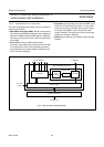
7.2.4 DATA INPUT FORMAT
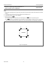
7.2.4.1 Interface definition
The data input interface uses 13 pins, all of which are
inputs (see Table 1). Pins YUV0 to YUV7 carry video and
synchronization data and 3 pins are reserved for control
purposes. Two separate clock inputs allow two different
signal sources to be used. The input clock can be
asynchronous to the SAA6752HS system clock.
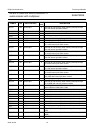
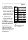
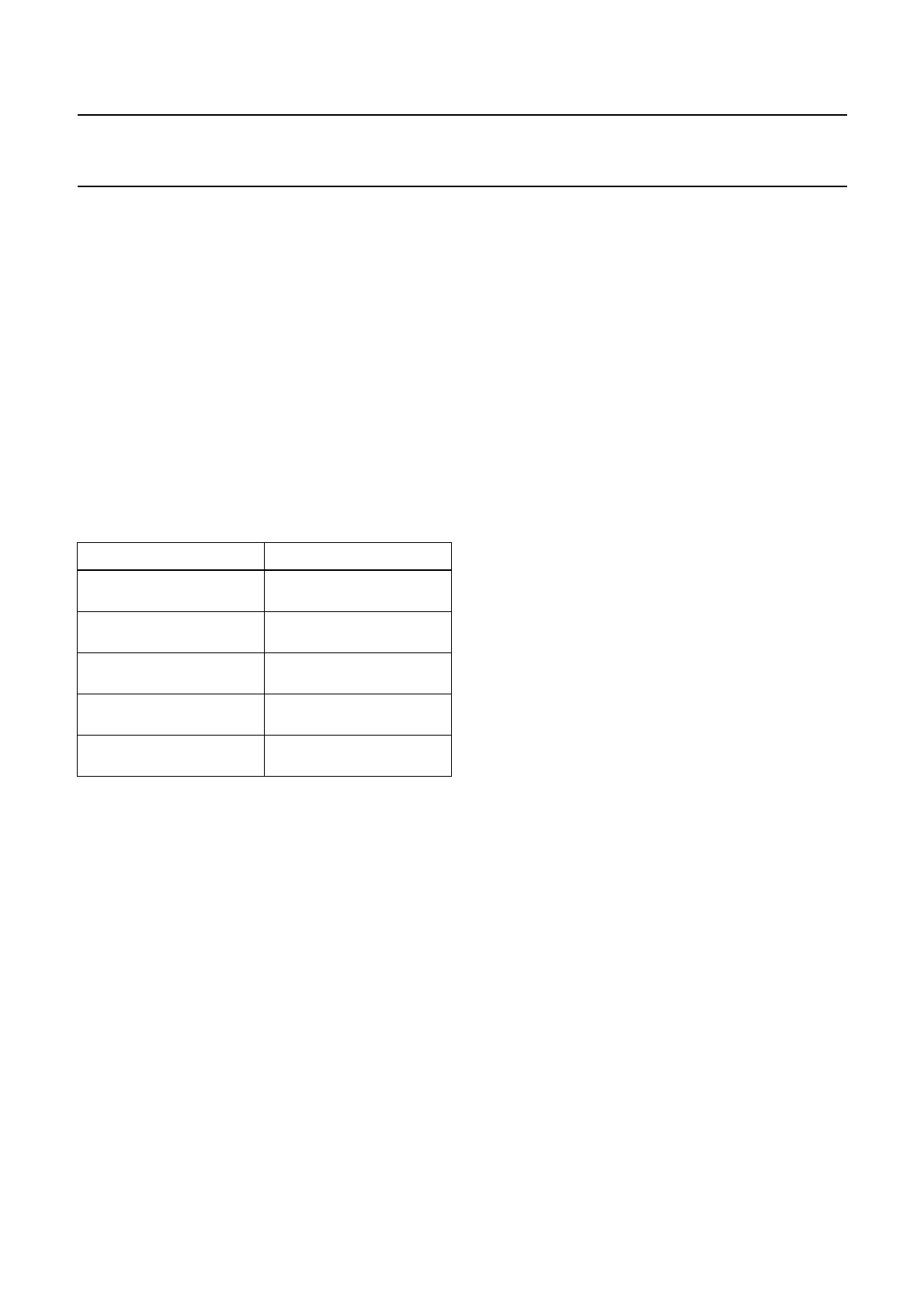
Table 1 List of pins data input port
Note
1. In ITU-T 656 mode sync signals are embedded in the
video data input stream. The external sync signals are
not used.
7.2.5 VIDEO SIGNAL PROCESSING
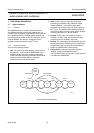
7.2.5.1 Acquisition of video data
Data is latched with the incoming video clock to provide
robust data capture. Video clock and data is unlocked to
the internal system clock therefore a clock domain bridge
is used. This is performed by oversampling of video clock
and data with 108 MHz.
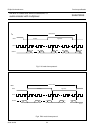
7.2.5.2 Sync decoding and filtering
To allow selection of the right portion of the video input
stream, synchronization signals from the stream are
recognized by a sync decoder. This checks the incoming
field (FID), vertical sync and horizontal sync. It is possible
to select either ‘internal synchronization’ (which means
that SAV/EAV codes in the ITU 601/656 video streams are
used) or externally applied hardware synchronization
signals (which are given by the video input processor).
In the latter case, 3 pin or 2 pin (V-sync and H-sync only)
synchronization can be used.
Using 2 pin synchronization, the FID information is given
by the timing of the transition of the V-sync. If a Vertical
Blanking Interval (VBI) starts during H-sync, the next field
will be the top field, otherwise it will be the bottom field.
A sync filter is used to inhibit sync signal triggering if an
incorrect number of pixels or lines has been input. It also
checks for the correct consecutive fields. The filter works
on three different levels. An H-sync is only accepted after
a predefined number of video cycles, a V-sync is only
accepted after a programmed number of lines and a field
is only accepted if top field follows bottom field or vice
versa.
7.2.5.3 Horizontal and vertical shift
This function is intended for correction in synchronization
of external sync signals if incorrectly timed. The amount of
shift is programmable via the I
2
C-bus.
7.2.5.4 SAV/EAV decoder
A SAV/EAV decoder extracts the F, V and H bits from the
video timing reference code. The decoder evaluates the
protection bits to be able to correct one bit errors within the
code word. If multiplebit errors are detected, the protection
bits are ignored and the field (F), vertical sync (V) and
horizontal sync (H) bits are directly extracted from the
code.
7.2.5.5 Video format conversion
The SAA6752HS converts the input video input signal to
the formats defined in Table 2 controlled by the I
2
C-bus
command. A 4 : 2 : 2 to 4 : 2 : 0 colour conversion is
performed as this is a pre-requisite of MPEG MP@ML
encoding.
PIN DESCRIPTION
YUV0 to YUV7 video input signal
(synchronous to VCLK)
FID odd/even field identification
signal; note 1
HSYNC horizontal synchronization
signal; note 1
VSYNC vertical synchronization
signal; note 1
VCLK1 or VCLK2 video clock signal (from
source 1 or 2)