


2004 Jan 26 38
Philips Semiconductors Product specification
MPEG-2 video and MPEG-audio/AC-3
audio encoder with multiplexer
SAA6752HS
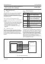
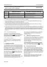
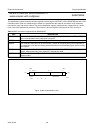
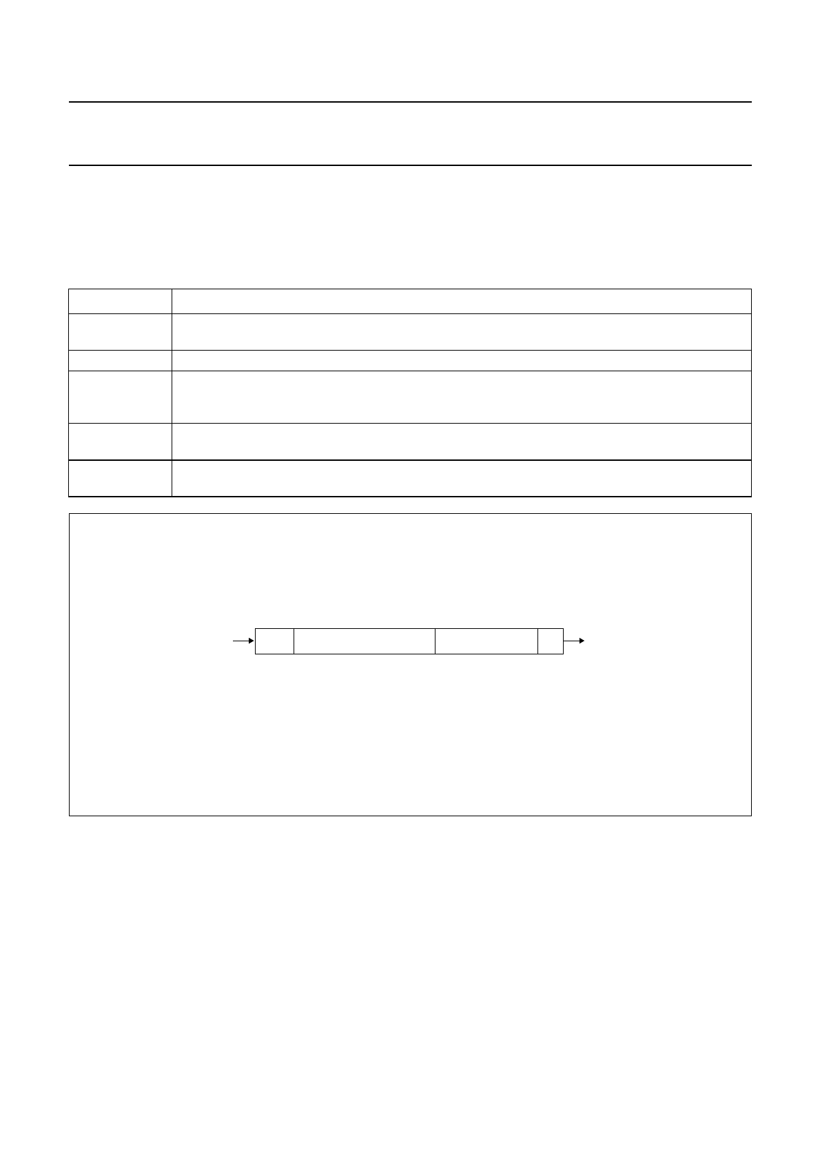
The identification register will load a component specific code during the CAPTURE_DATA_REGISTER state of the TAP
controller and this code can subsequently be shifted out. At board level this code can be used to verify component
manufacturer, type and version number. The device identification register contains 32 bits, numbered 31 to 0, where
bit 31 is the most significant bit (nearest to TDI) and bit 0 is the least significant bit (nearest to TDO); see Fig.14.
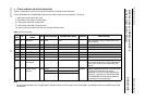
Table 12 BST instructions supported by the SAA6752HS
INST DESCRIPTION
BYPASS This mandatory instruction provides a minimum length serial path (1-bit) between TDI and TDO,
when no test operation of the component is required.
EXTEST This mandatory instruction allows testing of off-chip circuitry and board level interconnections.
SAMPLE This mandatory instruction can be used to take a sample of the inputs during normal operation of
the component. It can also be used to preload data values into the latched outputs of the boundary
scan register.
CLAMP This optional instruction is useful for testing, when not all ICs have BST. It addresses the bypass
register, while the boundary scan register is in external test mode.
IDCODE This optional instruction will provide information on the components manufacturer, part number and
version number.
handbook, full pagewidth
MHC141
XXXX 0010 1011 0110 0110 0000 0010 101
4-bit
version
code
16-bit part number
E M S
11-bit manufacturer
identification
1
31
MSB LSB
28 27 12
10
TDO
11
TDI
Fig.14 32 bits of identification code.