


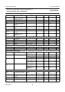
2004 Jan 26 62
Philips Semiconductors Product specification
MPEG-2 video and MPEG-audio/AC-3
audio encoder with multiplexer
SAA6752HS
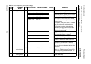
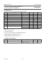
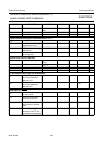
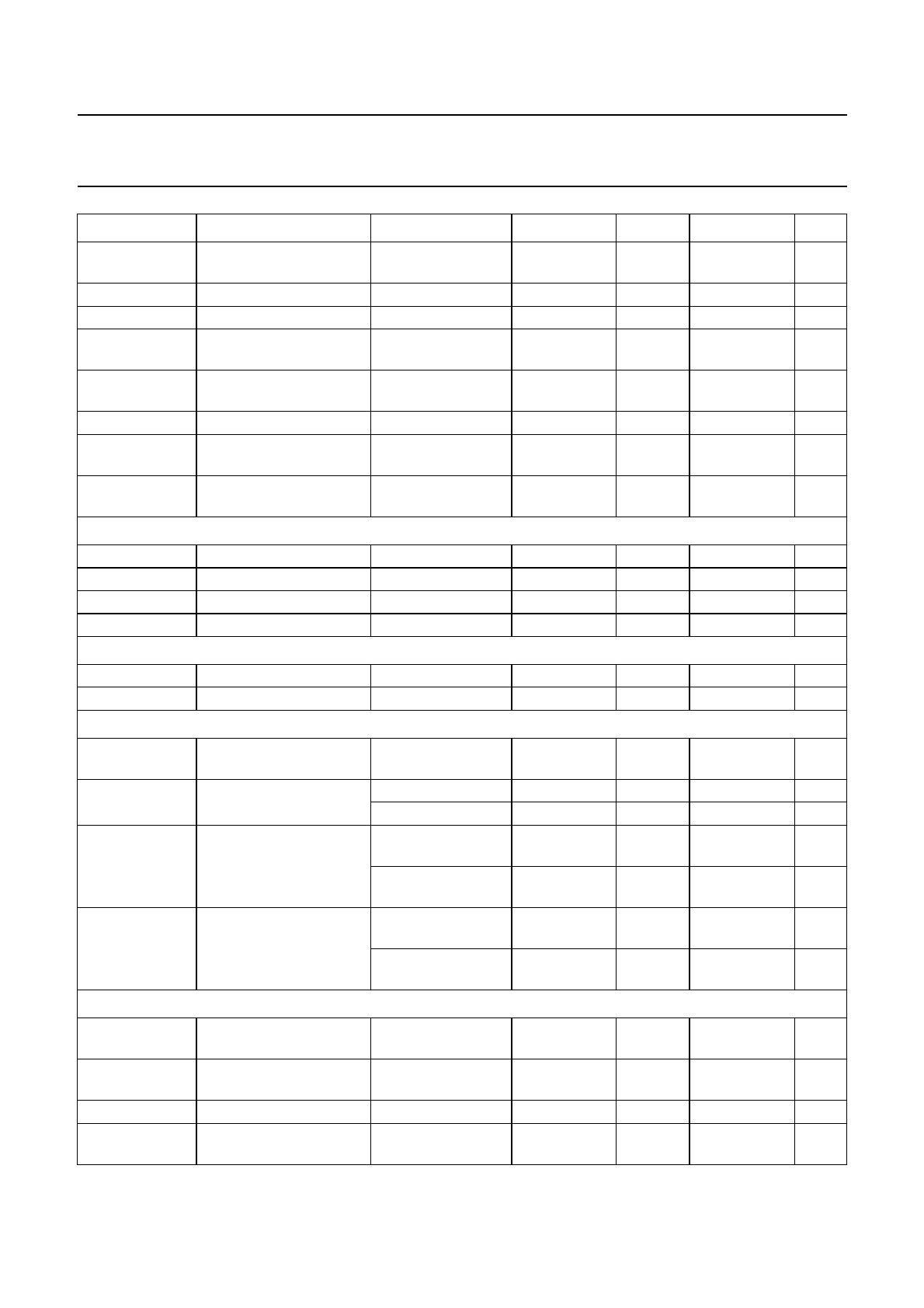
V
OL
LOW-level output
voltage; open-drain
3 mA sink current 0 − 0.4 V
t
LOW
SCL LOW time 1.3 −− µs
t
HIGH
SCL HIGH time 0.6 −− µs
t
r(I2C)
rise time of both SDA
and SCL
−−0.3 µs
t
f(I2C)
fall time of both SDA and
SCL
−−0.3 µs
t
SU;DAT
data set-up time 100 −− ns
t
HD;STA
hold time START
condition
0.6 −− µs
t
SU;STO
set-up time STOP
condition
0.6 −− µs
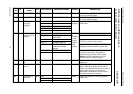
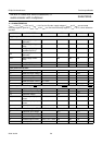
Video clock input timing: pins VCLK1 and VCLK2; see Fig.15
T
cy
cycle time 35 37 39 ns
δ duty factor t
HIGH
/T
cy
40 50 60 %
t
r(VCLK)
rise time V
I
= 0.8 to 2 V −−5ns
t
f(VCLK)
fall time V
I
= 2 to 0.8 V −−6ns
Video input data and control timing: pins YUV7 to YUV0, FID, HSYNC and VSYNC; see Fig.15
t
SU;DAT
data set-up time 6 −− ns
t
HD;DAT
data hold time 3 −− ns
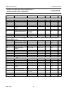
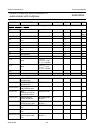
Video input parameter range
f
i(D)
data input frequency rate frame-locked;
notes 5 and 6
25.46 27 28.54 MHz
f
H
line frequency 625 lines; note 6 14734 15625 16515 kHz
525 lines; note 6 14837 15734 16631 kHz
f
V
field frequency 625 lines;
notes 7 and 8
46 50 50.75 kHz
525 lines;
notes 7 and 8
55 60 60.9 kHz
N
al/f
active lines/field 625 lines;
notes 7 and 9
265 288 311
525 lines;
notes 7 and 9
221 240 259
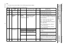
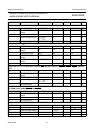
Crystal oscillator: pins XTALI and XTALO; note 10
f
XTAL
fundamental frequency note 11 27 ×
(1 − 80 × 10
−6
)
27 27 ×
(1+80× 10
−6
)
MHz
f
stab
MPEG2 frequency
stability
note 11 27 ×
(1 − 30 × 10
−6
)
− 27 ×
(1+30× 10
−6
)
MHz
C
L
load capacitance 8 10 12 pF
V
IL
LOW-level input voltage if used with external
clock
−0.5 − +0.7 V
SYMBOL PARAMETER CONDITIONS MIN. TYP. MAX. UNIT