


2004 Jan 26 37
Philips Semiconductors Product specification
MPEG-2 video and MPEG-audio/AC-3
audio encoder with multiplexer
SAA6752HS
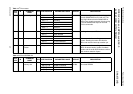
Notes
1. ‘No copy’ flag is only detected if the correct WSS VBI mode is enabled.
2. This error flag detects mismatches between the input video format (525 or 625) and SAA6752HS video setting
(525 or 625). Video syncs out of range are also detected.
3. A loss of video sync is flagged if 10 consecutive syncs are not detected.
4. For stream types which include video mode transitions to encode or idle/stop will not be finished, if no video is
present. A pending mode transition can be stopped by forced reconfigure.
5. In clock mode 1 and 3 this can occur due to discontinuity in the video input signal. In applications, which require an
exact ratio between the number of generated audio frames and the number of generated video frames, the host might
start a corrective action. In clock mode 3 this exception can be ignored; it will happen after some encoding time,
because the audio processing is locked to the system frequency and video processing depends on the video input
frequency.
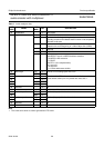
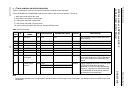
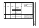
13 VBI WSS data has been captured SAA6752HS continues operation.
14 VBI CC data has been captured SAA6752HS continues operation.
15 memory manager resynchronization occurred
after discontinuity in the video input signal
SAA6752HS continues operation, but a forced
reconfigure is recommended.
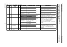
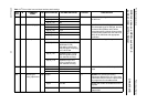
STATUS
WORD BIT
EXCEPTION CONDITION RESPONSE IF EXCEPTION IS DETECTED
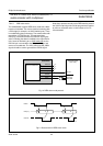
7.12.3 HOST INTERRUPT OPERATION
A LOW level as signalled by the host interface pin
indicates that an exception condition has been detected.
The host interrupt flag pin H_IRF is reset to HIGH by
reading the interrupt status word via the I
2
C-bus.
7.12.4 INTERRUPT MASKING
It is possible to mask any combination of exception
conditions by setting a 16-bit interrupt mask via the
I
2
C-bus.
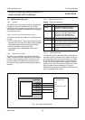
8 BOUNDARY SCAN TEST
The SAA6752HS has built-in logic and 5 dedicated pins to
support boundary scan testing, which allows board testing
without special hardware (nails). The SAA6752HS follows
the
“IEEE Std. 1149.1 - Standard Test Access Port and
Boundary Scan Architecture”
set by the Joint Test Action
Group (JTAG) chaired by Philips.
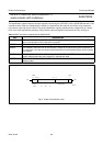
The 5 special pins are: Test Mode Select (TMS), Test
Clock (TCK), Test Reset (TRST), Test Data Input (TDI)
and Test Data Output (TDO).
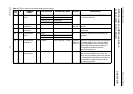
The Boundary Scan Test (BST) functions BYPASS,
EXTEST, SAMPLE, CLAMP and IDCODE are all
supported (see Table 12). Details on the JTAG BST-TEST
can be found in the specification “
IEEE Std. 1149.1”
.
A file containing the detailed Boundary Scan Description
Language (BSDL) description of the SAA6752HS is
available on request.
8.1 Initialization of boundary scan circuit
The Test Access Port (TAP) controller of an IC should be
in the reset state (TEST_LOGIC_RESET), when the IC is
in functional mode. This reset state also forces the
instruction register into a functional instruction such as
IDCODE or BYPASS.
To solve the power-up reset, the standard specifies that
the TAP controller will be forced asynchronously to the
TEST_LOGIC_RESET state by setting pin TRST to LOW.
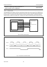
8.2 Device identification codes
A device identification register is specified in
“IEEE Std.
1149.1b-1994
”. It is a 32-bit register which contains fields
for the specification of the IC manufacturer, the IC part
number and the IC version number. Its biggest advantage
is the possibility to check for the correct ICs mounted after
production and determination of the version number of ICs
during field service.
When the IDCODE instruction is loaded into the BST
instruction register, the identification register will be
connected between TDI and TDO of the IC.