


2004 Jan 26 35
Philips Semiconductors Product specification
MPEG-2 video and MPEG-audio/AC-3
audio encoder with multiplexer
SAA6752HS
7.9.4 CLOCK MODE 2 AUTO-SWITCH
An auto-switch mode is available if Clock mode 2 is
selected. In this event the PLL will switch to Clock mode 1
or 3 if the conditions for Clock mode 2 are no longer met
(i.e. video frame frequency outside the range
1 ±200 × 10
−6
). The auto-switch preference is set by an
I
2
C-bus command during the SAA6752HS initialization.
If auto-switch occurs then a host interrupt can be flagged.
7.9.5 CRYSTAL TUNING
It is possible to tune the crystal frequency by up to
1 ±200 × 10
−6
via the I
2
C-bus. If necessary this can be
used to achieve the MPEG-2accuracy of 1 ±20 × 10
−6
with
standard crystals.
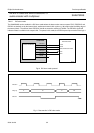
7.9.6 EXTERNAL CLOCK SOURCE
It is possible to use an external system clock. For start-up
before switching to the external clock input a crystal has to
be connected or the external frequency has to be applied
to pin XTALI. The input voltage for this pin must be limited
to 2.5 V. An external clock source cannot be used with
Clock mode 2.
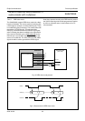
7.9.7 AUDIO CLOCK
A switchable sampling frequency for an audio
Analog-to-Digital Converter (ADC) is generated by the
internal PLL. Two sampling frequencies are selectable:
256 × 48 kHz and 384 × 48 kHz. This clock output can be
used as clock signal for an external audio ADC. The
system clock reference frequency as described in Table 9,
is used as reference for the internal PLL generating the
audio clock.
7.10 Power control and reset
7.10.1 GENERAL
An external reset pulse at power-up is needed to start-up
the SAA6752HS. This will start the oscillator and initialize
hardware and firmware. The SAA6752HS can be set to a
power saving sleep mode where all internal clocks are
switched off. In this mode restarting can only be done by a
hard reset pulse.
7.11 I
2
C-bus interface
7.11.1 GENERAL
The I
2
C-bus interface within the SAA6752HS is a slave
transceiver. It is used for all control settings. The read
mode may be used to read back error or status codes.
The I
2
C-bus interface is compliant to the I
2
C-bus standard
at 100 kHz and 400 kHz clock frequency and suitable for
bus line voltage levels of 3.3 V. If an I
2
C-bus with higher
voltage is used by an application, it is possible to add a
small interface between 3.3 V and a higher voltage level.
Only two MOSFET transistors (e.g. BSN10, BSN20 or
BSS83) are needed. A description of this circuit is
available at
http://www.semiconductors.philips.com/i2c/facts/
Information about the I
2
C-bus can be found in the
brochure
“The I
2
C-bus and how to use it”
(order number 9398 393 40011).
7.11.2 SLAVE ADDRESSES
Two write I
2
C-bus slave addresses (SAD) are available,
40H and 42H (8-bit), dependent on the state of address
select pin I2CADDRSEL. This avoids possible address
conflict of addresses with other devices. A HIGH-level at
the address selection pin will set the device write address
to 42H.
Similarly for read operations there are two slave
addresses: 41H and 43H. A HIGH-level at the address
selection pin will set the device read address to 43H.
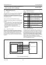
7.12 Exception handling
7.12.1 GENERAL
The SAA6752HS is capable of flagging certain events to a
host via a host interrupt flag pin H_IRF. The host is able to
read back a 16-bit status word via the I
2
C-bus to identify
the specific event and take action accordingly. Detectable
events include copyright violations, loss of input
synchronization, DVD compliance errors etc.
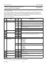
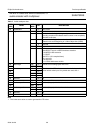
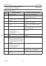
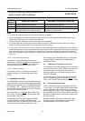
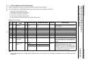
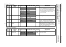
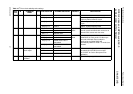
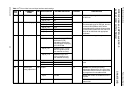
7.12.2 EXCEPTION CONDITIONS
A list of the SAA6752HS exception conditions, as
indicated by the status word, is defined in Table 11. The
I
2
C-bus subaddress is 12H (see Table 14).