


44 ST1000 Plus & ST2000 Plus Tiller Pilots - Owner’s Handbook
4 Installing the Tiller Pilot
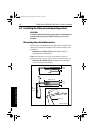
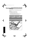
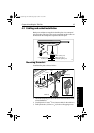
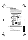
Mounting the pedestal socket
1. Mark the mounting ring’s position on the cockpit seat or counter.
2. Ensure that control dimensions A and B are correct.
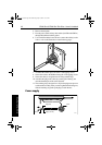
3. Mark the bolt holes on the mounting ring and then drill three
6 mm (
1
/
4
in) diameter holes.
4. Bed the mounting ring on a thin coat of silicon sealant.
5. Use three 6 mm (
1
/
4
in) diameter bolts, nuts and washers to attach
the mounting ring to the backing plate (with the backing plate on
the other side of the mounting surface, as shown above).
6. Screw the mounting socket firmly into place.
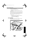
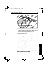
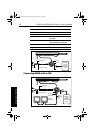
Note: When the tiller pilot is not in use, you can unscrew the complete
rod assembly to leave the cockpit unobstructed.
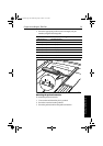
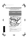
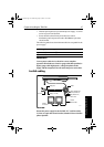
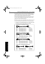
Alternative tiller pins
Your Raymarine dealer can also supply the following alternative
lengths of tiller pin for other non-standard installations.
Dimension G Pedestal socket length L Part no.
64 mm (2.5 in) Standard dimension -
102 mm (4.0 in) 38 mm (1.5 in) D026
114 mm (4.5 in) 50 mm (2.0 in) D027
127 mm (5.0 in) 64 mm (2.5 in) D028
140 mm (5.5 in) 76 mm (3.0 in) D029
153 mm (6.0 in) 89 mm (3.5 in) D030
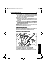
Description Size Part no.
Small threaded tiller pin 25 mm (1.0 in) D014
Extra length tiller pin 72 mm (2.8 in) D020
Extra length threaded tiller pin 72 mm (2.8 in) D021
81130_3.book Page 44 Wednesday, July 25, 2001 11:57 AM