


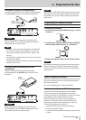
TASCAM DR-100MKII
17
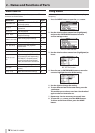
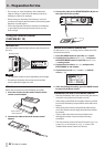
r
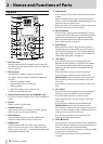
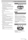
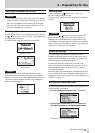
Loop playback IN (starting) and OUT (ending)
points
The settings of loop playback starting (IN) and ending
(OUT) points are shown. When the starting (IN) point
is set, the icon appears below the corresponding
position on the playback position bar.
When the ending (OUT) point is set, the icon
appears below the corresponding position on the
playback position bar
t
Playback file number/total number of files
The total number of les in the playback area and the
number of the current le are shown.
y
Monitoring output
Depending on the status, one of the following icons
appears.
Sound output from the headphone jack
Sound output from the speaker
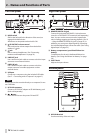
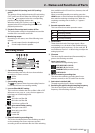
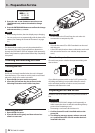
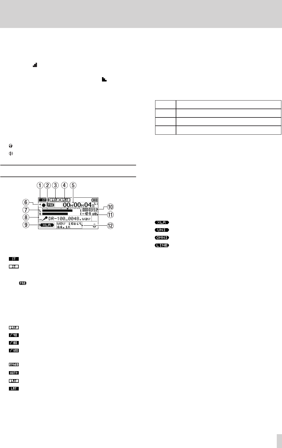
Recording screen
1 Stereo/mono setting
When recording with mics, this icon shows whether
recording is in stereo or mono.
Stereo
Mono
2
Prerecording setting
The icon appears when the prerecording function
is “ON” and the unit is in recording standby.
3
Low-cut filter ON/OFF setting
This icon shows whether the low-cut lter is ON or OFF.
When set to
40Hz
,
80Hz
or
120Hz
, the icon appears as
light letters on a dark background.
OFF
40 Hz low-cut lter ON
80 Hz low-cut lter ON
120 Hz low-cut lter ON
4
Auto gain control/limiter setting
Auto gain control OFF
Auto gain control ON
Limiter OFF
Limiter ON
5 Elapsed/remaining recording time
This shows the elapsed time of the le being recorded
or the remaining time (hours: minutes: seconds)
according to the set maximum le size. If the remaining
time available on the SD card is less, however, that will
be shown instead.
When in recording standby or recording, press the
HOME button to switch between the elapsed recording
time and the remaining recording time. When the
remaining recording time is shown, a “–” appears
before it.
6 Recorder operation status
This icon shows the recorder operation status.
Icon Meaning
8
Recording standby
9
Recording paused
0
Currently recording
7
Level meters
These show the levels of the input signals. When
overdubbing is on, the levels of the combined input
and playback signals are shown. On the scale, the b
mark indicates a level of −16 dB to help you adjust the
analog input level.
8
File name
This shows the le name that will automatically be
given to the le being recorded.
9
Input signal setting
This icon shows the signal being input.
XLR (MIC/LINE 1) IN L/R
UNI MIC L/R (directional)
OMNI MIC L/R (omnidirectional)
LINE 2 IN L/R
0 SD card remaining recording time
This shows the remaining recording time (hours:
minutes: seconds) on the SD card in the recorder.
q
Peak value in decibels (dB)
The peak recording level is shown in decibels.
w Recording file type/bit length/sampling frequency
This shows the format, bit length and sampling
frequency of the le being recorded.
2 – Names and Functions of Parts