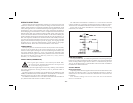
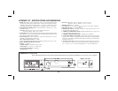
MODULE #4 - PROGRAM DIGITAL FILTER AND REMOTE INPUT
PROGRAM DIGITAL FILTERING
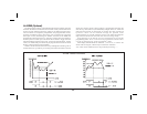
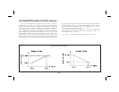
If the displayed process signal is difficult to read due to small process
variations or noise, increased levels of filtering will help to stabilize the
display. This programming step may be used in conjunction with display
roundingprogramming(Pro1&2)tohelpminimizethiseffect.Althoughthe
digital filter features a “moving window” to help minimize response time,
higher degrees of filtering levels will have slightly longer response times.
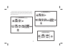
“FILter” < > “0” - no digital filtering
“1” - normal filtering
“2” - increased filtering
“3” - maximum filtering
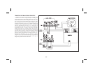
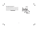
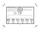
PROGRAM FUNCTION OF E1-CON AND OPTIONAL E2-CON
The function ofthe remoteinput “E1-CON” (TBA #4)and, ifthe totalizer
option is installed, the remote input “E2-CON” (TBA #8) are the same.
Functions are activated, as described in the appropriate function, when
connected to signal common (TBA #7). Whether a function is edge or level
activated, it must be held low for a minimum of 20 msec in order for the
functiontooccur.Theremoteinputpinscanbeusedsimultaneouslyandwith
any combination of functions. When pins are tied together and activated,
E1-CON function is generally performed first.
“E1-CON”< > “0”- If the Totalizer/Peak/Valley/Display Offset option is
installed, a negative going edge offsets the displayed
temperaturetozero.(AtthetimetheE-Pinisactivated,
the value of the actualtemperature beingdisplayed is
placed in the location of the display offset value. To
bring the unit into the normal temperature display
mode,resettheoffsetvaluetozeroviathefrontpanel.)
“1” - A negative going edge resets the contents of the
totalizer to zero. Totalization commences regardless
of the state of the remote input.
“2” - A negative going edge resets the contents of the
totalizer to zero and allows totalization as long as the
input is low. If the input goes high, totalization is
stopped and the contents are saved. This acts as a
totalization enable control from Time 1 to Time 2.
“3” - A low level allows totalization as long as the input is
low. If the input goes high, totalization is stopped and
the contents are saved. This acts as a totalization
enable control from Time 1 to Time 2.
“4”-Alowlevelholdsthedisplay(displayhold).Whilethis
input is low, the indicator continues to process the
input signal and drive the alarms, totalizer, etc., with
theactual signal. Thecontents of thetotalizer areheld
at the same time the input display is held.
Note: If display hold is activated, and input value is
requested via serial, the value on the display will be
sent instead of the actual input value at that time.
“5”-Anegativegoingedgeresetsbothpeakandvalley buffers.
Note:IfP/V iscalledup, achangewill notappearon the
display until the next time the P/V is called up.
“6” - A negative going edge resets only the peak buffer and
the indicator enters a peak reading display mode as
long as the input is low. If the input goes high, peak
detection and indication are stopped and the last peak
reading is retained.
“7”-Anegativegoingedgeresetsonlythevalleybufferand
the indicator enters a valley reading display mode as
long as the input is low. If the input goes high, valley
detectionandindicationarestoppedandthelastvalley
reading is retained.
“8” - If the alarm option is installed, a negative going edge
resets the latched alarm(s).
-11-