


20 mA CURRENT LOOP SERIAL COMMUNICATIONS (Optional)
GENERAL DESCRIPTION
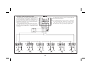
The serial communication option is a half-duplex, two-way, 20 mA loop
thatcanconnect toavariety ofprinters,computers,terminals andcontrollers
to suit manydata-polling or automatic operation applications. The indicator
respondstoahostofcommands,includingchangealarmvalue,resettotalizer
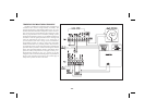
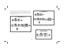
and transmitinput value. Two loopsare required for all hook-ups;a transmit
(out-goingdata)loopandareceive(in-comingdata)loop.Sincetheindicator
monitors the receive loop for a busy signal (current interrupted) while
transmitting, the receive loop must be connected even if the indicator is
transmittingonly,suchas toaprinter.Abuilt-in 20mAsourcecan beusedin
the transmit loop (only) by connecting the current return wire to -20 mA
SRC., instead of SO+. To bypass the built-in current source, make transmit
loopconnectionstoSO+andSO-. Additionally,multipleunitsandotherRed
Lion Controls instruments can be serially addressed, up to a maximum of 99
units. (The actual number in a single loop is limited by the serial hardware
specifications.)Toeliminateproblemswithgroundloops,theserialcircuitry
isisolated fromboth signalcommon andoutput common.Optional 20mA to
RS232Cand20mAtoRS422convertermodulesexpandtheunit’sflexibility.
Note: When operating the unit with a printer, the receive loop of the indicator
must have current flowing into it before transmission can take place.
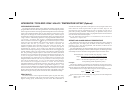
COMMUNICATION FORMAT
Data is sent byswitching current on and off in theloop andis received by
monitoring the switching action and interpreting the codes that are
transmitted. In order for data to be correctly interpreted, there must be
identical formats and baud rates among the communicating equipment. The
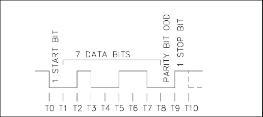
onlyformatavailable withthisindicator is1startbit, 7databits, 1oddparity
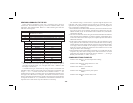
bitand 1 stopbit. The baudrates are programmableand the choicesare: 300,
600, 1200 and 2400.
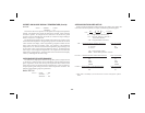
Before serial communication can take place, the indicator must be
programmedtothesamebaudrateastheconnectedequipment.Inaddition,the
loop address number, print options and full or abbreviated transmission must
beprogrammed.Ifonly oneindicatoristobe used,thenaloopaddress number
of“0”maybyused,toeliminatetherequirementfortheaddressspecifierwhen
sending a command. If more than one indicator is on the loop, assignment of
unique addresses, other than zero, for each indicator is recommended. Valid
addressesof 0to 99may beassigned, butthe built-incurrent source,if used,is
capableofdrivingupto7units.Additionaldrivecapabilitymaybeaffordedby
an external current source with a higher compliance voltage. Refer to
programming section “Pro 7” to program the serial option.
-27-
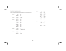
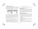
DATA FORMAT-10 BIT FRAME [300, 600, 1200, 2400 Baud]