


RECEIVING DATA FROM THE IMY
Dataistransmitted fromtheindicator whenevera“T” or“P” commandis
received via serial communications or a remote input, E1-CON or optional
E2-CONpin is programmed forprint request, isactivated. If the abbreviated
transmission was programmed, just data will be transmitted with no built-in
delay. (If full transmission is programmed, then there is a 400 msec min to
800 msec max delay built-in to the string.)
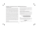
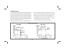
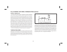
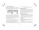
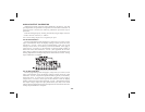
A data string transmission is shown below.
Thefirsttwocharacterstransmittedaretheunitaddressnumber,unlessitis
zero, in which case it is left blank. Then two blank spaces are sent.The next
threecharactersaretheabbreviationforthevalue(mnemonics),whichisthen
followed by a blank. The actual data is transmitted next. The field is right
justified withleading zeros. Negative numbersare indicated by aminus sign
fixed next to the identifier. A carriage return and a line feed are transmitted
next. For various reasons, “extra” characters are added onto the end of the
abovecharacterstring. (Thesecharacterscould beandare usedforcontrolor
signaling purposes.) These characters are:
< CR> sent after single line transmissions from IM unit.
< SP>< CR>< LF> sent after “last line of a block” transmission from IM.
For a “T” command or after each “line of a block” transmission, no
additionalcharacters aresent.If theabbreviatedtransmission isselected,the
address, mnemonics, and any blank spaces (first eight characters) are not
transmitted (the data strings are left justified in this case).
If the transmitted data is overrunning the peripheral’s buffer, the receive
channel to the indicator may be used for handshaking purposes. As a
consequenceofthis,eveniftheindicator istotransmitonly(ex.toaprinter),
current must be flowing in the receive channel to allow transmission.
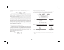
Examples of transmissions are as follows:
2 INP -125.7F < CR> < LF > full transmission
-125.7 < CR> < LF > abbreviated transmission
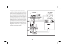
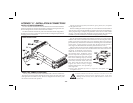
CURRENT LOOP INSTALLATION
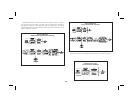
WIRING CONNECTIONS
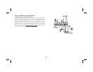
When wiring the 20 mA current loop, remove the bottom terminal block
(TBA), located on the rear of the unit. Refer to the numbers listed with the
terminal descriptions belowor those located on the label. It isrecommended
that shielded (screened) cable be used for serial communications. This unit
meets the EMC specifications using Alpha #2404 cable or equivalent. There
are higher grades of shielded cable,such as fourconductor twistedpair, that
offeran even higherdegree ofnoise immunity. Installeach wirein its proper
location on the terminal block. When all connections are made, replace the
terminal block into its proper location.
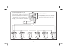
SERIAL TERMINAL DESCRIPTIONS
8.PRINTREQ.-ThePrintRequestterminalispulledlowtoactivatetheunit
totransmitdataaccordingtotheprintfunctionselectedinProgramModule
#7 (Reference Programming Module #7 for more details). In order for a
print request function to occur, E1-CON (TBA #4) or E2-CON (TBA #8)
must be programmed for print request. Note: In order to guarantee a
print-out, the programmed E-CON pin must be held low for at least 20
msec. If this time exceeds 800 msec, a second print-out may occur.
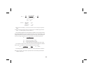
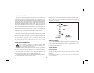
9. -20 mA SRC. - 20 mA current source return path for the transmit loop.
Current flows into this pin.
10. SI+ (Serial In+) -
11. SI- (Serial In-) -
The unit receives commands on the SI terminals. They are connected in
serieswiththetransmitoroutputterminalsofthedevicetobeconnected.
12.SO+/+20mASRC.(SerialOut+)-20mAcurrentsourceforthetransmit
loop (internally connected).
13. SO- (Serial Out-) -
The unit transmits the requested data on the SO terminals. They are
connected in series to the receive input of the device to be connected.
Note: The Serial Input terminals must be held in the mark condition (current
flowing)inorderfortheunittorespondtoaPrintRequestterminalactivation.
-30-