APPENDIX “A” - INSTALLATION & CONNECTIONS
INSTALLATION ENVIRONMENT
Theunitshouldbeinstalledinalocationthatdoesnotexceedthemaximum
operatingtemperatureandprovidesgoodaircirculation.Placingtheunitnear
devices that generate excessive heat should be avoided.
Thebezelshouldbecleanedonlywithasoftclothandneutralsoapproduct.
DoNOTusesolvents.Continuous exposuretodirectsunlightmayaccelerate
the aging process of the bezel.
Do not use tools of any kind (screwdrivers, pens, pencils, etc.) to operate
the keypad of the unit.
BeforeinstallingtheIMintothe panel,theusershouldfirstbecomefamiliar
with the unit. It may also be desirable to program the unit for the application.
When programming is complete, all parameters will be saved in non-volatile
memory. The Program Disable (PGM.DIS.) terminal should be connected to
COMM. to prevent accidental or unauthorized programming changes.
-35-
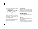
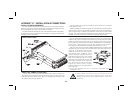
PANEL INSTALLATION
Theunit meetsNEMA 4/IP65requirements forindoor use,when properly
installed.The units are intendedto be mountedinto an enclosed panelwith a
gasket to provide a water-tight seal. Two mounting clips and screws are
providedforeasyinstallation.Considerationshouldbegiventothethickness
of the panel. A panel which is too thin may distort and not provide a
water-tight seal. Recommended minimum panel thickness is 1/8".)
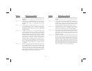
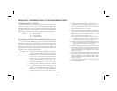
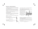
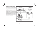
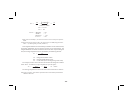
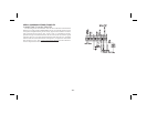
After the panel cut-out has been completed and deburred, carefully slide
thegasketover therearoftheunit tothebackof thebezel.Insertthe unitinto
the panel. As depicted in the drawing,
install the screws into the narrow end of
the mounting clips. Thread the screws
into the clips until the pointed end just
protrudes through the other side. Install
each of the mounting clips by inserting
the wide lip of the clipsinto thewide end
of the hole, located on either side of the
case. Then snap the clip onto the case.
Tighten the screws evenly to apply
uniform compression, thus providing a
water-tight seal.
Caution: Only minimum pressure is required to seal panel. Do NOT
overtighten screws.
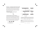
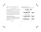
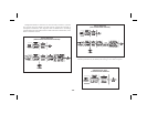
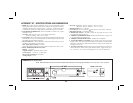
SELECT AC POWER (115/230 VAC)
TheACpowertotheunitmustbeselectedforeither115VACor230VAC.
The selector switch is located through an access slot on the side of the case
(Seefigure above orlabel oncase). The unitis shippedfrom the factorywith
the switch in the 230 VAC position.
Caution: Make sure the AC selector switch is set to the
appropriate position before applying power to the unit.
Damage to the unit may occur if the AC selector switch is set
incorrectly.