


SERIAL COMMUNICATIONS EXAMPLES
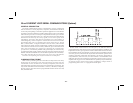
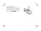
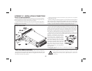
CONNECTING TO AN RLC PRINTER
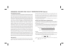
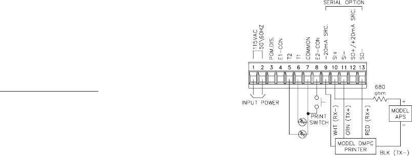
The drawing shows the indicator with the 20 mA Serial Communication
Optionset-up withanRLC ModelDMPC printer.Anexternal currentsource
is required to implement the printer’s busy signal to the indicator’s receive
loop, which prevents overruns. The “Print switch” is a momentary contact,
push button type connected between the E2-CON (TBA #8) and the signal
common (TBA #7). The print function and E2-CON must be pro- grammed
and the baud rate must match those of the printer. If a printer is used which
does not have a ‘busy’ line, current must still beflowing
into the indicator’s
receive loop before transmission can occur.
-31-