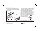
WIRING CONNECTIONS
After the unithas been mechanically mounted, itis ready to be wired. All
conductors should meet voltage and current ratings for each terminal. Also
cabling should conform to approriate standards of good installation, local
codes, and regulations. It is recommended thatpower suppliedto the unitbe
protected by a fuse or circuit breaker. All wiring connections are made on
removableplug-in terminalblocks. Thereis aseparate terminalblock forthe
bottom board (TBA) and optional top board (TBB). When wiring the unit,
remove the terminal block and use the numbers on the label to identify the
positionnumberwiththeproperfunction.Stripthewire,leavingapprox.1/4"
bare wire exposed (stranded wires should be tinned with solder). Insert the
wire into the terminal and tighten down the screw until the wire is clamped
tightly. Each terminal can accept up to one 14-gauge, two 18-gauge or four
20-gauge wire(s). After the terminal block is wired, install it into proper
location on the PC board. Wire each terminal block in this manner.
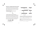
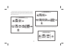
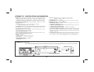
POWER WIRING
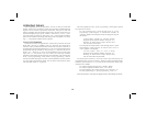
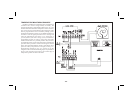
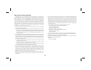
PrimaryACpowerisconnectedtoterminal1and2(markedVAC50/60Hz,
located on the left hand side of the bottom terminal block). To reduce the
chance of noise spikes entering the AC line and affecting the indicator, the
AC power should be relatively “clean” and within the specified ±10%
variationlimit.Drawingpowerfromheavilyloadedcircuitsorcircuitswhich
also power loads that cycle on and off, (contactors, relays, motors,
machinery, etc.) should be avoided.
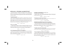
SIGNAL WIRING (THERMISTOR)
Meter signal input common is not isolated from PGM. DIS.,
E1-CON,E2-CON; maximumallowable 50 Vcan bepresent in
the circuit that is being measured.
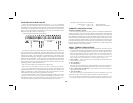
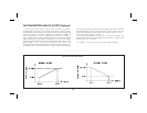
Thermistors provide a higher degree of accuracy, stability, and resolution
over other temperature sensing elements, such as platinum RTDs or
thermocouples.
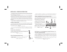
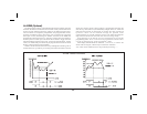
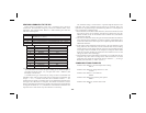
The IMY supports two popular types of thermistors; the 400 Series (YSI
44000) 2,252W thermistor, and the700 Series “Thermolinearä”thermistor.
Selection of the two types is done in Programming Module #1.
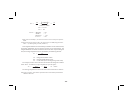
The400Series thermistorisa 2-wiresensor.Onelead connectstoTBA #6
(T1) and the other lead connects to TBA #7 (comm).
The 700 Series Thermolinearä thermistor is a 3-wire sensor. One lead
connects to TBA#6 (T1)and the common leadconnects toTBA #7 (comm).
ThethirdwireisanadditionalthermistorleadandconnectstoTBA#5(T2).
Always refer to the sensor manufacturer’s instructions for probe wiring
connections, if available.
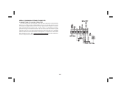
USER INPUT WIRING
Userinputs(PGM.DIS.,E1-CON,andoptionalE2-CON)aredigitalinputs
thatareactivewhenconnectedto TBA#5Common.Anyformofmechanical
switch, sinking collector logic with less than 0.7 V saturation may be used.
The use of shielded cable is recommended. Follow the EMC Installation
Guidelines for shield connection.
OUTPUT WIRING
Relay Connections
Toprolongcontactlifeandsuppresselectricalnoiseinterferenceduetothe
switching of inductive loads, it is good installation practice to install a
snubber across the contactor. Follow the manufacturer’s instructions for
installation.
Note: Snubber leakage current can cause some electro-mechanical
devices to be held ON.
-37-
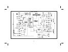
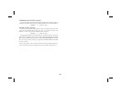
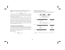
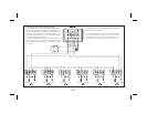
A.C. Powered Basic Connection