


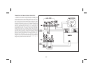
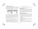
ALARMS (Optional)
The alarm option consists of an additional printed circuit board with nine
terminals.SixoftheseterminalsarethetwoForm-Crelaysandtheotherthree
are the two open collector transistors, which act in parallel with the relays.
The two alarms are completely independent with programmable values,
hysteresis (deadband), high or low acting, auto or manual reset, triggering
from input or total, and tracking one another, if desired. If the alarms are
programmed tolatch (manual reset),then they will haveto be reset eitherby
the front panel or remote input. The alarms can be made to trigger from the
integrator/totalizer instead of the input, to activate external alarms, control
valves,etc.Additionally,thealarmsmaybeprogrammedtoactivateanalarm
display to alert operators of the condition.
Alarm#1canbemadetotrackAlarm#2byenablingalarmtracking.Thisis
usefulinalarmset-upswhereapre-warningcontrolactivatesbeforeasecond
alarm shuts off the process. When tracking is programmed, changing the
shut-off trip value (Alarm #2) automatically changes Alarm #1 so that the
offset between Alarm #2 and Alarm #1 remains the same. Alarm and
hysteresis values can be modified through the optional serial
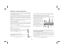
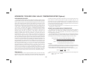
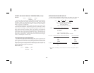
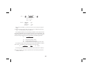
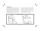
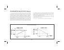
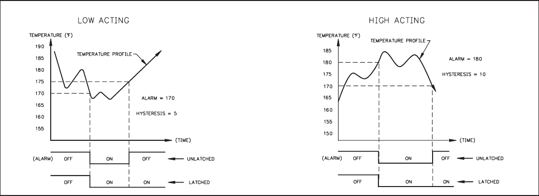
communications to provide automatic control. The following diagrams
depict how the alarms work with both “HI” and “LO” acting set-ups.
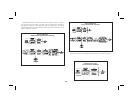
Programming of the alarms can be accomplished in the normal
programmingmode“Pro6”ortheunitcanbeprogrammedsothatthevalues
can only be changed in the “quick programming” mode.
Ifthedisplayshouldindicatean“OLOLOL”,“ULULUL”,or“SHort”the
alarms will de-energize, whether they are latched or unlatched.
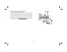
Note: Alarm Comm. (TBB #8) must be kept isolated from analog “-”.
-26-
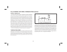
ALARM TIMING DIAGRAMS