ANALOG OUTPUT CALIBRATION
Although the analog output has been calibrated at the factory, zero and
span adjustments are provided to compensate for small offsets and drifts. If
excessive drift is noticed, the following calibration procedure may be
performed.
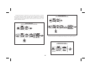
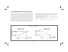
Scale the analog output by entering an arbitrarily larger display value for
“AN-HI” then for “AN-LO”, in “PRO 8”.
Note: Set the analog output source assignment for input.
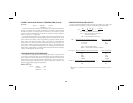
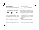
4 to 20 mA Calibration
Exit the programming modeand applya (temperature)/(resistance) to the
input of the indicator so that the display reading is below that of the value
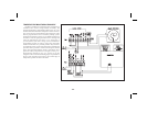
entered for “AN-LO”. Adjust the zero potentiometer (right side) so that
exactly 4.00 mA flows, as verified by an accurate ammeter. Next, apply a
(temperature)/ (resistance) to the indicator so that the display reading is
above that of the value entered for “AN-HI”. (See Appendix “B” for max.
input voltage.) Adjust the span potentiometer (left side) so that 20.00 mA is
flowing.Repeatthezeroandspanadjustmentsuntilbothareaccurate.Analog
output calibration is complete.
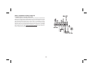
0 to 10 VDC Calibration
Exit the programming mode and apply a (temperature)/(resistance) to the
input of the indicator so that the display reading is below that of the value
enteredfor“AN-LO”.Adjustthezeropotentiometer(rightside)sothatexactly
0.00 VDC flows, as verified by an accurate voltmeter. Next, apply a
(temperature)/ (resistance) to the input of the indicator so that the display
readingisabove thatofthe valueenteredfor“AN-HI”. (SeeAppendix“B” for
max. input voltage.) Adjust the span potentiometer (left side) so that 10.00
VDCis flowing.Repeat thezero and spanadjustments until bothare accurate.
Analog output calibration is complete.
-34-