


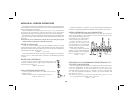
MODULE #6 - PROGRAM ALARM/SETPOINT
If the alarm option is installed, this module is used to configure the
operation of the alarms to a variety of combinations. The programmable
optionsareHI/LO acting,auto/manualreset(latching), tracking,assignment
to input or integrator/totalizer, display alarms, alarm values and hysteresis
(deadband) values.
ALARM TRACKING
With alarm tracking, whenever alarm #2 is changed, alarm #1 will also
change so that the offset between alarm #2 and alarm #1 remains the same.
This is useful for hierarchical setpoints (pre-alarm and alarm) when one
change applies to both alarm values. When programming from the front
panel, tracking only occurs when PGM. DIS. is low (front panel lock-out
mode, alarm #1 will not appear). Tracking will always occur if alarm #2 is
modified via serial communications independent of PGM. DIS.
“trAc” < > “yES” or “NO”
DISPLAY ALARMS
Ifdisplay alarmsaredesired, a messagewill flash onthe display every5-10
secs when an alarm activates. For alarm 1, the message will flash “AL1 ON”
andalarm2willflash“AL2ON”.Thiswarnsanoperatorofanalarmcondition.
The message will stop when the unit is no longer in an alarm condition.
“dISP” < > “yES” or “NO”
AUTO OR MANUAL RESET FOR ALARM #1
The reset action of alarm #1 may be programmed to reset automatically
(unlatched) or be programmed to require a manual reset (latched), through
either a remote input (E1-CON or optional E2-CON) or through the front
panel. Latched alarms are usually used when an operator is required to take
some action for the alarm condition.
“LAtC-1” < > “yES” or “NO”
ALARM #1 ASSIGNMENT TO INPUT OR
INTEGRATOR/TOTALIZER
Alarm #1 may be programmed to activate on either the input or the
integrator/totalizer value. If the integrator/totalizer option is not installed,
this step defaults to the input.
“ASN-1” < > “INPUt” or “totAL”
PROGRAM VALUE FOR ALARM #1
The range of the alarm value is -999 to 9,999 for the input display and
-99999 to 999999 for the totalizer option display.
“AL-1” < > “-999” to “9999”
PROGRAM HYSTERESIS VALUE FOR ALARM #1
(Cannot be programmed if alarm latch is programmed)
The hysteresis(deadband) value for alarm #1may beprogrammed from 1
to 9,999 for the input and 1 to 999999 for the totalizer option. The value is
either added to or subtractedfrom thealarm value depending on whether the
alarm is high or low acting. (See “alarm” section for operation.)
“HyS-1” < > “1” to “9999”
ALARM #1 HIGH OR LOW ACTING
Theactionofalarm#1maybeprogrammedtoactivateeitherwhenthedisplay
value goes above the alarm value (high acting) or goes below it (low acting).
“Act-1” < > “HI” or “LO”
AUTO OR MANUAL RESET FOR ALARM #2
The reset action of alarm #2 may be programmed to reset automatically
(unlatched) or be programmed to require a manual reset (latched), through
either a remote input (E1-CON or optional E2-CON) or through the front
panel. Latched alarms are usually used when an operator is required to take
some action for the alarm condition.
“LAtC-2” < > “yES” or “NO”
-14-