EMC INSTALLATION GUIDELINES
Although this unit is designed with a high degree of immunity to
ElectroMagneticInterference (EMI),proper installationand wiringmethods
must be followed to ensure compatibility in each application. The type of
electrical noise,source or coupling method into theunit maybe different for
various installations. In extremely high EMI environments, additional
measuresmaybe needed.Theunit becomesmoreimmuneto EMIwithfewer
I/O connections. Cable length, routing and shield termination are very
importantandcanmeanthedifferencebetweenasuccessfuloratroublesome
installation. Listed below are some EMC guidelines for successful
installation in an industrial environment.
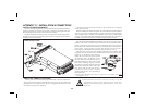
1. The unit should be mounted in a metal enclosure, which is properly
connected to protective earth.
a. If the bezel is exposed to high Electro-Static Discharge (ESD) levels,
above4Kv, itshould beconnectedto protectiveearth.This canbedone
bymakingsurethemetalbezelmakespropercontacttothepanelcut-out
or connecting the bezel screw with a spade terminal and wire to
protective earth.
2.Useshielded(screened)cablesforallSignalandControlinputs.Theshield
(screen) pigtail connection should be made as short as possible. The
connection point for the shield depends somewhat upon the application.
Listed below are the recommended methods of connecting the shield, in
order of their effectiveness.
a. Connect the shield only at the panel where the unit is mounted to earth
ground (protective earth).
b. Connect the shield to earth ground at both ends of the cable, usually
when the noise source frequency is above 1 MHz.
c. Connect the shield to commonof theunit andleave theother end ofthe
shield unconnected and insulated from earth ground.
3.NeverrunSignalorControlcablesinthesameconduitorracewaywithAC
power lines, conductors feeding motors, solenoids, SCR controls, and
heaters, etc. The cables should be run in metal conduit that is properly
grounded. This is especially useful in applications where cable runs are
long and portable two-way radios are used in close proximity or if the
installation is near a commercial radio transmitter.
4.SignalorControlcableswithinanenclosureshouldberoutedasfarawayas
possible from contactors, control relays, transformers, and other noisy
components.
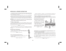
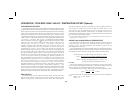
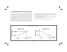
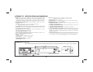
5.In extremelyhigh EMIenvironments, theuseof externalEMI suppression
devices, such as ferrite suppression cores, is effective. Install them on
Signal and Control cables as close to the unit as possible. Loop the cable
through the core several times or use multiple cores on each cable for
additionalprotection.Installlinefiltersonthepowerinputcabletotheunit
tosuppresspowerlineinterference.Installthemnearthepowerentrypoint
of the enclosure. The following EMI suppression devices (or equivalent)
are recommended:
Ferrite Suppression Cores for signal and control cables:
Fair-Rite # 0443167251 (RLC #FCOR0000)
TDK # ZCAT3035-1330A
Steward #28B2029-0A0
Line Filters for input power cables:
Schaffner # FN610-1/07 (RLC #LFIL0000)
Schaffner # FN670-1.8/07
Corcom #1VR3
Note:Referencemanufacturer’sinstructionswheninstallingalinefilter.
6.Long cable runsare more susceptibleto EMI pickupthan short cableruns.
Therefore, keep cable runs as short as possible.
7. Switching of inductive loads produces high EMI. Use of snubbers across
inductive loads suppresses EMI.
Snubbers:
RLC #SNUB0000
-36-