


Removing a PCIe mezzanine card
Removing the Network Daughter Card
Removing the IDSDM card
Removing the rSPI card
Replacing the SD vFlash card
Replacing the internal USB key
Installing the system board
Prerequisites
CAUTION: Many repairs may only be done by a certified service technician. You should only
perform troubleshooting and simple repairs as authorized in your product documentation, or as
directed by the online or telephone service and support team. Damage due to servicing that is
not authorized by Dell is not covered by your warranty. Read and follow the safety instructions
that came with the product.
NOTE: You must remove the system board to replace a faulty system board.
1. Ensure that you read the Safety instructions.
2. Keep the #2 Phillips screwdriver and the Hex nut driver-5 mm ready.
3. Remove the system board. See Removing the system board.
4. Unpack the new system board assembly.
CAUTION: Do not lift the system board assembly by holding a memory module, processor, or
other components.
CAUTION: Take care not to damage the system identification button while placing the system
board into the chassis.
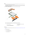
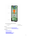
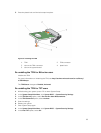
Steps
1. Hold the system board by its edges and align the USB connectors with the slots on the front wall of
the chassis.
2. Lower the system board until the system board is firmly seated on the chassis.
3. Install the screws to secure the system board to the chassis.
Next steps
1. Install the Trusted Platform Module (TPM). For information on how to install TPM, see Installing the
Trusted Platform Module .For information on TPM, see Trusted Platform Module.
2. Install the following:
a. internal USB key
b. SD vFlash card
c. IDSDM/rSPI card
d. NDC/LOM riser card
e. PCIe mezzanine card
f. PCIe extender/storage controller card
g. hard-drive/SSD cage
h. hard-drive/SSD backplane
92