


June 2014
12
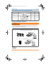
Quick Start Guide
Step 5: Wire, ground, and power up
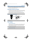
Use of copper wire of sufficient size to ensure that the voltage across the
transmitter power terminals does not drop below 9 vdc. Power supply voltage
can be variable, especially under abnormal conditions such as when operating on
battery backup. A minimum of 12 vdc under normal operating conditions is
recommended. Shielded twisted pair Type A cable is recommended.
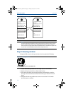
1. To power the transmitter, connect the power leads to the terminals indicated
on the terminal block label.
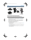
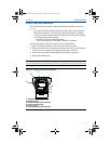
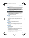
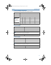
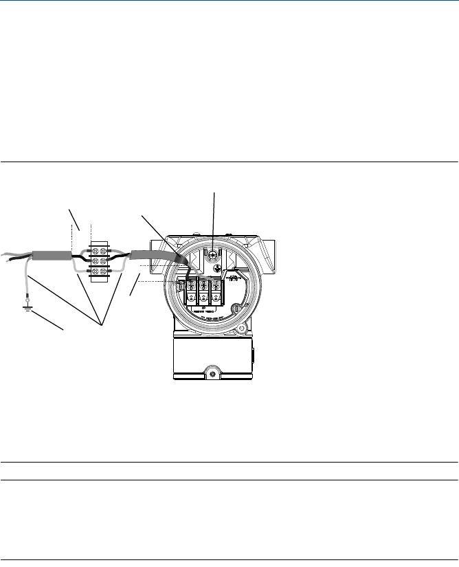
Figure 9. Wiring Terminals
A. Minimize distance
B. Trim shield and insulate
C. Protective Grounding Terminal (do not ground cable shield at the transmitter)
D. Insulate Shield
E. Minimize distance
F. Connect Shield Back to the Power Supply Ground
Note
The 3051 power terminals are polarity insensitive, which means the electrical polarity of the power
leads does not matter when connecting to the power terminals. If polarity sensitive devices are
connected to the segment, terminal polarity should be followed. When wiring to the screw
terminals, the use of crimped legs is recommended.
2. Tighten the terminal screws to ensure adequate contact. No additional power
is needed.
Signal wiring grounding
Do not run signal wiring in conduit or open trays with power wiring, or near heavy
electrical equipment. Grounding terminations are provided on the outside of the
electronics housing and inside the Terminal Compartment. These grounds are
used when transient protect terminal blocks are installed or to fulfill local
regulations.
1. Remove the Field Terminals housing cover.
2. Connect the wiring pair and ground as indicated in Figure 9.
DP
A
E
D
F
B
C
00825-0100-4774_RevFA.fm Page 12 Friday, June 6, 2014 2:21 PM