


9
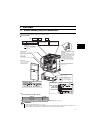
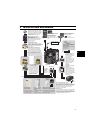
Wiring
2
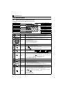
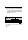
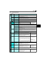
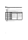
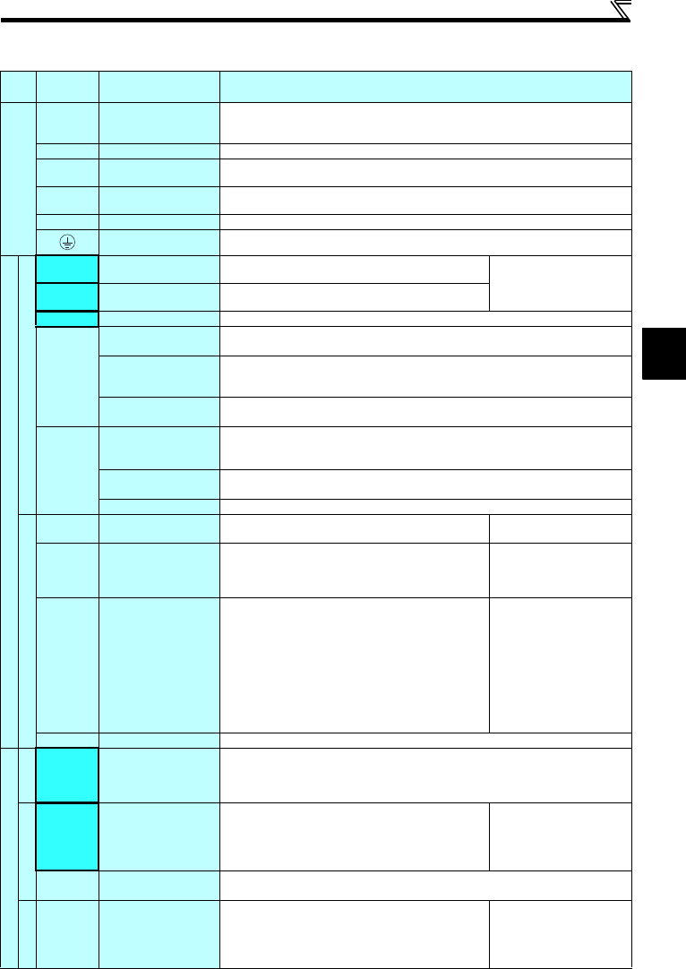
2.3.2 Terminal specifications
Type
Terminal
Symbol
Terminal Name Terminal Specification
Main circuit terminal
R/L1, S/L2,
T/L3
AC power input
Connect to the commercial power supply.
Do not connect anything to these terminals when using the high power factor converter (FR-HC)
or power regeneration common converter (FR-CV).
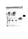
U, V, W Drive unit output
Connect a dedicated PM motor.
P/+, PR Brake resistor connection
Connect a brake resistor (FR-ABR, MRS type, MYS type) across terminals P/+ and PR.
(The brake resistor can not be connected to the 0.2K.)
P/+, N/- Brake unit connection
Connect the brake unit (FR-BU2), power regeneration common converter (FR-CV) or high power
factor converter (FR-HC).
P/+, P1 DC reactor connection
Remove the jumper across terminals P/+ and P1 and connect a DC reactor.
Earth (Ground) For earthing (grounding) the drive unit chassis. Must be earthed (grounded).
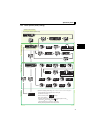
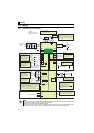
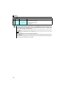
Control circuit terminal/Input signal
Contact input
STF Forward rotation start
Turn ON the STF signal to start forward rotation and turn it OFF
to stop.
When the STF and STR signals
are turned ON simultaneously,
the stop command is given.
STR Reverse rotation start
Turn ON the STR signal to start reverse rotation and turn it
OFF to stop.
RH, RM, RL Multi-speed selection Multi-speed can be selected according to the combination of RH, RM and RL signals.
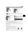
SD
Contact input common
(sink) (initial setting)
Common terminal for contact input terminal (sink logic) and terminal FM.
External transistor
common (source)
Connect this terminal to the power supply common terminal of a transistor output (open collector
output) device, such as a programmable controller, in the source logic to avoid malfunction by
undesirable current.
24VDC power supply
common
Common output terminal for 24VDC 0.1A power supply (PC terminal).
Isolated from terminals 5 and SE.
PC
External transistor
common (sink)
(initial setting)
Connect this terminal to the power supply common terminal of a transistor output (open collector
output) device, such as a programmable controller, in the sink logic to avoid malfunction by
undesirable current.
Contact input common
(source)
Common terminal for contact input terminal (source logic).
24VDC power supply
Can be used as 24VDC 0.1A power supply.
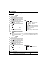
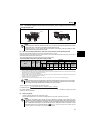
Speed setting
10
Speed setting power
supply
Used as power supply when connecting potentiometer for
speed setting (speed setting) from outside of the drive unit.
5VDC
permissible load current 10mA
2 Speed setting (voltage)
Inputting 0 to 5VDC (or 0 to 10V) provides the maximum
rotation speed at 5V (10V) and makes input and output
proportional. Use Pr. 73 to switch between input 0 to 5VDC
input (initial setting) and 0 to 10VDC.
Input resistance10kΩ ± 1kΩ
Permissible maximum voltage
20VDC
4 Speed setting (current)
Inputting 4 to 20mADC (or 0 to 5V, 0 to 10V) provides the
maximum rotation speed at 20mA and makes input and output
proportional. This input signal is valid only when the AU signal
is ON (terminal 2 input is invalid). To use terminal 4 (initial
setting is current input), set "4" in any of Pr.178 to Pr.182 (input
terminal function selection) to assign the function, and turn ON
AU signal.
Use Pr. 267 to switch among input 4 to 20mA (initial setting), 0
to 5VDC and 0 to 10VDC. Set the voltage/current input switch
in the "V" position to select voltage input (0 to 5V/0 to 10V).
Current input:
Input resistance 249Ω ± 5Ω
Maximum permissible current
30mA
Voltage input:
Input resistance10kΩ ± 1kΩ
Permissible maximum voltage
20VDC
5 Speed setting common Speed setting signal (terminal 2, 4) common terminal. Do not earth (ground).
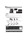
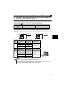
Control circuit terminal/Output signal
Relay
A, B, C
Relay output
(fault output)
1 changeover contact output indicates that the drive unit’s protective function has activated and
the output stopped.
Fault: discontinuity across B-C (continuity across A-C),
Normal: continuity across B-C (discontinuity across A-C)
Open collector
RUN Drive unit running
Switched Low when the drive unit rotation speed is equal to or
higher than the 1r/min. Switched High during stop or DC
injection brake operation.
(Low is when the open collector output transistor is ON (conducts).
High is when the transistor is OFF (does not conduct).)
Permissible load 24VDC
(maximum 27VDC) 0.1A
(a voltage drop is 3.4V maximum
when the signal is ON)
SE
Open collector output
common
Common terminal of terminal RUN.
Pulse
FM For meter
Used to output a selected monitored item (such as Rotation
speed) among several monitored items.
(Not output during drive unit reset.)
The output signal is proportional to the magnitude of the
corresponding monitored item.
Permissible load current 1mA
1440 pulses/s at 3000r/min