


35
Check first when you have a trouble
7
7.3 Check first when you have a trouble
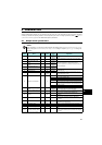
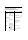
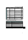
Fault
PU disconnection
yA communication error has occurred between
the PU and the drive unit.
yThe communication interval has exceeded the
permissible time period during RS-485
communication via the PU connector.
yThe number of communication errors has
exceeded the number of retries.
yConnect the parameter unit cable securely.
yCheck the communication data and communication settings.
yIncrease the Pr. 122 PU communication check time interval
setting. Or set "9999" (no communication check).
Retry count excess *2
Operation restart within the set number of retries
has failed.
Eliminate the cause of the error preceding this error indication.
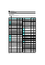
CPU fault
An error has occurred in the CPU and in the
peripheral circuits.
yTake measures against noises if there are devices producing
excess electrical noises around the drive unit.
yIf the situation does not improve after taking the above
measure, please contact your sales representative.
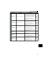
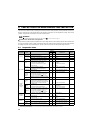
/
Output current detection
value exceeded *2
Output current has exceeded the output current
detection level that is set in the parameter.
Check the settings of Pr. 150 Output current detection level, Pr.
151 Output current detection signal delay time, Pr. 166 Output
current detection signal retention time, and Pr. 167 Output current
detection operation selection.
Inrush current limit
circuit fault
The resistor of the inrush current limit circuit has
overheated.
Configure a circuit where frequent power ON/OFF is not
repeated.
If the situation does not improve after taking the above
measure, please contact your sales representative.
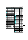
Analog input fault
A voltage(current) has been input to terminal 4
when the setting in Pr. 267 Terminal 4 input
selection and the setting of voltage/current input
switch are different.
Give a speed command by a current input or set Pr. 267
Terminal 4 input selection, and set the voltage/current input
switch to voltage input.
Overspeed occurrence
The motor speed has exceeded the Pr. 374
Overspeed detection level .
Check that the Pr. 374 Overspeed detection level value is correct.
PID signal fault
PID upper limit (FUP), PID lower limit (FDN), or
PID deviation limit (Y48) has turned ON.
Make correct settings for Pr.131 PID upper limit, Pr.132 PID
lower limit, Pr. 553 PID deviation limit.
E.SAF
yAn internal circuit fault has occurred.
yEither the contact between terminals S1 and
SC or terminals S2 and SC has opened.
Short across the terminals S1 and SC and the terminals S2
and SC with shortening wires.
∗1 Resetting the drive unit initializes the internal cumulative heat value of the electronic thermal relay function.
∗2 This protective function is not available in the initial status.
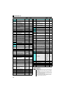
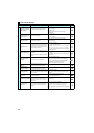
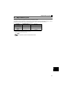
Description Countermeasure
Motor does not start. Check start and speed command sources and enter a start command (STF, etc.) and a speed command.
Motor or machine is making abnormal acoustic noise.
Take EMC measures if a steady operation cannot be performed due to EMI. Alternatively, set the Pr.74
Input filter time constant setting higher.
Drive unit generates abnormal noise. Install the fan cover correctly.
Motor generates heat abnormally. Clean the motor fan. Improve the environment.
Motor rotates in the opposite direction.
Connect phase sequence of the output cables (terminal U, V, W) to the motor correctly.
Check the rotation direction specification of the motor's output shaft.
Alternatively, check the connection of the start signal. (STF: forward rotation, STR: reverse rotation)
Speed greatly differs from the setting. Check the settings of Pr.1Maximum setting, Pr.2 Minimum setting, and calibration parameters C2 to C7.
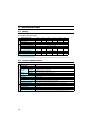
Acceleration/deceleration is not smooth.
Reduce the load. Alternatively, increase the acceleration/deceleration time.
Make adjustments to situate the machine equipment in a more stable place.
Eliminate the load fluctuation. Use Pr.156 Stall prevention operation selection to disable stall prevention
operation.
Speed varies during operation. Check the speed setting signals.
Operation mode is not changed properly. Turn OFF the start signal (STF or STR). Check if Pr.79 Operation mode selection is set appropriately.
Operation panel display is not operating. Check the wiring and the installation.
Speed does not accelerate. Check the settings of Pr.1 Maximum setting, Pr.2 Minimum setting, and calibration parameters C2 to C7.
Unable to write parameter setting. Check Pr.77 Parameter write selection.
* For further information on troubleshooting, refer to the
Instruction Manual (Applied).
Function Name Description Countermeasure Display