


15
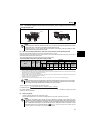
Connection of a dedicated external brake resistor (MRS type, MYS type, FR-ABR) (0.4K or higher)
2
2.4 Connection of a dedicated external brake resistor (MRS type,
MYS type, FR-ABR) (0.4K or higher)
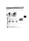
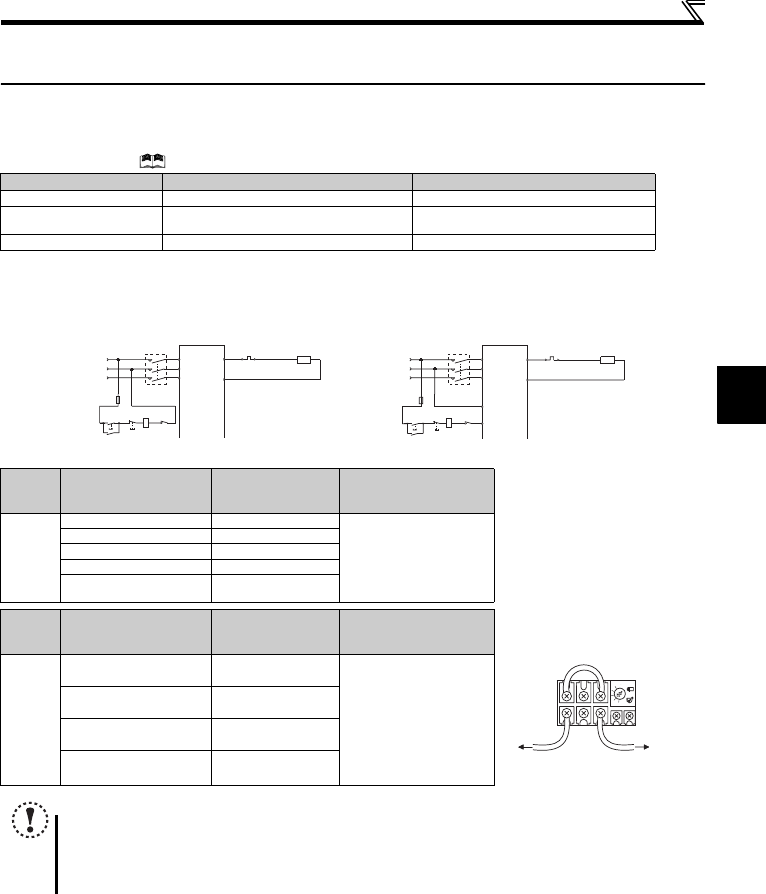
Install a dedicated brake resistor (MRS type, MYS type, FR-ABR) outside when the motor driven by the drive unit is made to
run by the load, quick deceleration is required, etc. Connect a dedicated brake resistor (MRS type, MYS type, FR-ABR) to
terminal P/+ and PR. (For the locations of terminal P/+ and PR, refer to the terminal block layout (page 11).)
Set parameters below. (
Refer to the Instruction Manual (Applied) for the parameter details.)
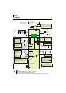
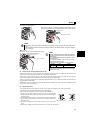
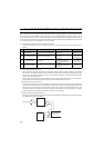
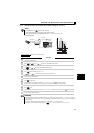
z It is recommended to configure a sequence, which shuts off power in the input side of the drive unit by the external thermal
relay as shown below, to prevent overheat and burnout of the brake resistor (MRS type, MYS type) and high duty brake
resistor (FR-ABR) in case the regenerative brake transistor is damaged. (The brake resistor cannot be connected to the
0.2K.)
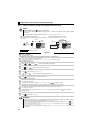
* Refer to the table below for the type number of each capacity of thermal relay and the diagram below for the connection.
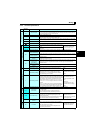
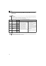
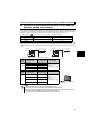
Connected Brake Resistor Pr. 30 Regenerative function selection Setting Pr. 70 Special regenerative brake duty Setting
MRS type, MYS type 0 (initial value) —
MYS type
(used at 100% torque/6%ED)
16%
FR-ABR 1 10%
Power
Supply
Voltage
Brake Resistor
Thermal Relay Type
(Mitsubishi product)
Contact Rating
200V
MRS120W200 TH-N20CXHZ-0.7A
110VAC 5A,
220VAC 2A(AC11 class)
110VDC 0.5A,
220VDC 0.25A(DC11 class)
MRS120W100 TH-N20CXHZ-1.3A
MRS120W60 TH-N20CXHZ-2.1A
MRS120W40 TH-N20CXHZ-3.6A
MYS220W50
(two units in parallel)
TH-N20CXHZ-5A
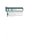
Power
Supply
Voltage
High-duty
Brake Resistor
Thermal Relay Type
(Mitsubishi product)
Contact Rating
200V
FR-ABR-0.4K TH-N20CXHZ-0.7A
110VAC 5A,
220VAC 2A(AC11 class)
110VDC 0.5A,
220VDC 0.25A(DC11 class)
FR-ABR-0.75K TH-N20CXHZ-1.3A
FR-ABR-2.2K TH-N20CXHZ-2.1A
FR-ABR-3.7K TH-N20CXHZ-3.6A
NOTE
y The brake resistor connected should only be the dedicated brake resistor.
y Perform wiring and operation according to the Instruction Manual of each option unit.
y
Brake resistor cannot be used with the brake unit, high power factor converter, power supply regeneration converter, etc.
y Do not use the brake resistor(MRS type, MYS type) with a lead wire extended.
y Do not connect a resistor directly to terminals P/+ and N/-. This could cause a fire.
MC
Drive unit
MC
R
PR
P/+
S/L2
T/L3
R/L1
OFF
ON
OCR
Contact
Power supply
F
<Example 1>
MC
High-duty brake
resistor (FR-ABR)
Thermal relay
(OCR) (*)
Drive unit
MC
R
PR
P/+
S/L2
T/L3
R/L1
OFF
ON
B
C
Power supply
F
<Example 2>
MC
High-duty brake
resistor (FR-ABR)
OCR
Contact
MC
Thermal relay
(OCR) (*)
To the drive unit
terminal P/+
To a resisto
r
TH-N20
1/L1 5/L3
2/T1 6/T3