


10
Wiring
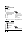
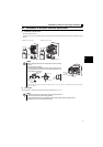
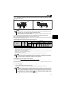
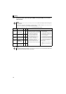
Communication
— PU connector
With the PU connector, communication can be established through RS-485.
yConforming standard: EIA-485 (RS-485)
yTransmission format: Multidrop link
yCommunication speed: 4800 to 38400bps
yOverall length: 500m
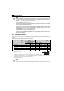
NOTE
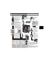
y To change the input specification for terminal 4, set Pr. 267 and the voltage/current input switch correctly, then input
the analog signal relevant to the setting. Applying a voltage with voltage/current input switch in "I" position (current
input is selected) or a current with switch in "V" position (voltage input is selected) could cause component damage
to the drive unit or analog circuit of output devices.
y Connecting the power supply to the drive unit output terminals (U, V, W) will damage the drive unit. Do not perform
such wiring.
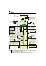
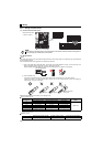
y indicates that terminal functions can be selected using Pr. 178 to Pr. 182, Pr. 190, Pr. 192, Pr. 197 (I/O terminal
function selection).
y The terminal names and functions shown here are the initial settings.
y The terminals S1, S2, SC, and SO are for manufacturer setting. Do not connect anything to these. Doing so may cause
a drive unit failure.
Do not remove the shortening wires across the terminals S1 and SC and the terminals S2 and SC. Removing either of
these shortening wires disables the drive unit operation.
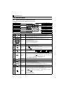
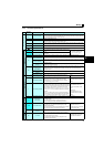
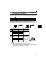
Type
Terminal
Symbol
Terminal Name Terminal Specification