


16
PRECAUTIONS FOR USE OF THE DRIVE UNIT
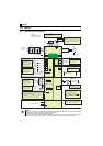
3 PRECAUTIONS FOR USE OF THE DRIVE UNIT
The FR-D700-G series is a highly reliable product, but incorrect peripheral circuit making or operation/handling method may
shorten the product life or damage the product.
Before starting operation, always recheck the following items.
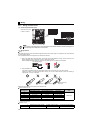
(1) Use crimping terminals with insulation sleeve to wire the power supply and motor.
(2) Application of power to the output terminals (U, V, W) of the drive unit will damage the drive unit. Never perform
such wiring.
(3) After wiring, wire offcuts must not be left in the drive unit.
Wire offcuts can cause an alarm, failure or malfunction. Always keep the drive unit clean.
When drilling mounting holes in an enclosure etc., take care not to allow chips and other foreign matter to enter the drive
unit.
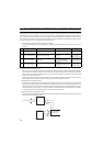
(4) Use cables of the size to make a voltage drop 2% or less.
If the wiring distance is long between the drive unit and motor, a main circuit cable voltage drop will cause the motor
torque to decrease especially at the output of a low speed. Refer to page 14 for the recommended wire sizes.
(5) The overall wiring length should be 30m or less.
Especially for long distance wiring, or the equipment connected to the output side may malfunction or become faulty
under the influence of a charging current due to the stray capacity of the wiring. Therefore, note the overall wiring length.
(Refer to page 15)
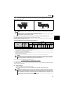
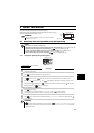
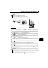
(6) Electromagnetic wave interference
The input/output (main circuit) of the drive unit includes high frequency components, which may interfere with the
communication devices (such as AM radios) used near the drive unit. In this case, install the FR-BIF optional capacitor
type filter (for use in the input side only) or FR-BSF01 or FR-BLF line noise filter to minimize interference.
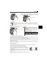
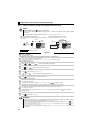
(7) Do not install a power factor correction capacitor, surge suppressor or capacitor type filter on the drive unit
output side.
This will cause the drive unit to trip or the capacitor and surge suppressor to be damaged. If any of the above devices are
connected, immediately remove them.
(8) For some short time after the power is switched OFF, a high voltage remains in the smoothing capacitor.
When accessing the drive unit for inspection, wait for at least 10 minutes after the power supply has been switched OFF,
and then make sure that the voltage across the main circuit terminals P/+ and N/- of the drive unit is not more than
30VDC using a tester, etc.
(9) A short circuit or earth (ground) fault on the drive unit output side may damage the drive unit module.
y Fully check the insulation resistance of the circuit prior to drive unit operation since repeated short circuits caused by
peripheral circuit inadequacy or an earth (ground) fault caused by wiring inadequacy or reduced motor insulation
resistance may damage the drive unit module.
y Fully check the to-earth (ground) insulation and phase to phase insulation of the drive unit output side before power-
On.
Especially for an old motor or use in hostile atmosphere, securely check the motor insulation resistance etc.
(10) Do not use the drive unit input side magnetic contactor to start/stop the drive unit.
Since repeated inrush currents at power ON will shorten the life of the converter circuit (switching life is about 1,000,000
times.), frequent starts and stops of the MC must be avoided. Turn ON/OFF the drive unit start controlling terminals (STF,
STR) to run/stop the drive unit. ( Refer to the Instruction Manual (Applied))
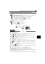
(11) Across terminals P/+ and PR, connect only an external brake resistor.
y Do not connect a mechanical brake.
y The brake resistor cannot be connected to the 0.2K. Do not connect anything to terminals P/+ and PR.
Also, never short between these terminals.