


1
1
1 OUTLINE
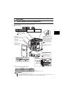
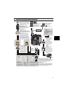
1.1 Product checking and parts identification
Unpack the drive unit and check the capacity plate on the front cover and the rating plate on the drive unit side face to ensure
that the product agrees with your order and the drive unit is intact.
zDrive unit model
• Accessory
· Fan cover fixing screws (M3
×
35mm)
These screws are necessary for compliance with the EU Directive.
(
Refer to page 41
)
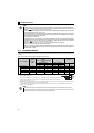
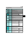
Capacity Quantity
0.2K to 0.75K none
1.5K to 3.7K 1
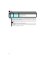
REMARKS
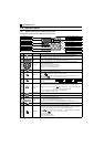
y For how to find the SERIAL number, refer to page 44.
y Caution stickers are enclosed with this instruction manual. These caution stickers include stickers that are used for the
automatic restart after instantaneous power failure function, which are not required for FR-D700-G.
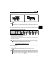
FR
--
Symbol Voltage class
D720 1.5
-
G
Represents the drive
unit capacity [kW]
Represents the S-PM
geared motor drive
K
D720
Three-phase 200V class
Capacity plate
Drive unit model
Serial number
Rating plate
Drive unit model
Input rating
Output rating
Serial number
D720 G
DRIVE UNIT
DATE:XXXX-XX
Production year and month
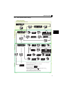
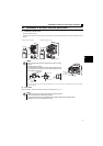
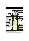
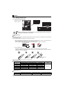
Control circuit terminal block
(Refer to page 9)
Control logic switchover jumper
connector
The jumper connector is in the sink
logic (SINK) when shipped from the
factory. Move the jumper connector
to change to the source logic
(SOURCE). Always fit the jumper
connector to the either position.
( Refer to the Instruction Manual
(Applied))
Combed shaped wiring cover
Refer to the Instruction
Manual (Applied) for installation/
removal.
Main circuit terminal block
(Refer to page 9)
Front cover
Refer to the Instruction
Manual (Applied) for
installation/removal.
PU connector
(Refer to page 8)
Voltage/current input switch
(Refer to page 8)
Operation panel
(Refer to page 2)
Cooling fan
The cooling fan is removable.
( Refer to the Instruction
Manual (Applied))