


2
Operation panel
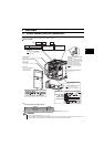
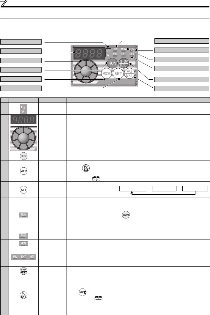
1.2 Operation panel
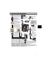
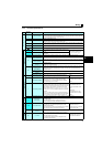
1.2.1 Names and functions of the operation panel
The operation panel cannot be removed from the drive unit.
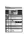
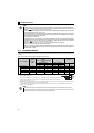
No. Component Name Description
(a)
Unit indicator
Hz: Lit to indicate frequency. (Flickers when the set frequency monitor is displayed.)
A: Lit to indicate current.
(Both "Hz" and "A" are lit to indicate a value other than frequency or current. )
(b)
Monitor (4-digit
LED)
Shows the speed, parameter number, etc.
(To monitor the output power, the set speed and other items, set Pr. 52.)
(c) Setting dial
The dial of the Mitsubishi drive unit. The setting dial is used to change the speed and
parameter settings.
Press to display the following.
y Displays the set speed in the monitor mode
y Present set value is displayed during calibration
y Displays the order in the faults history mode
(d)
Start command Select the rotation direction in Pr. 40.
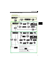
(e) MODE key
Used to switch among different setting modes.
Pressing simultaneously changes the operation mode.
Holding this key for 2 seconds locks the operation. The key lock is invalid when Pr. 161 = "0
(initial setting)." Refer to the Instruction Manual (Applied)
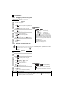
(f) SET key
Used to enter a setting.
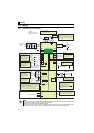
If pressed during the operation,
monitored item changes as the
following:
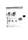
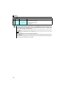
(g)
Operation status
indicator
Lit or flickers during drive unit operation.
*
* Lit: When the forward rotation operation is being performed.
Slow flickering (1.4s cycle): When the reverse rotation operation is being performed.
Fast flickering (0.2s cycle): When has been pressed or the start command has been
given, but the operation cannot be made.
yWhen the speed command is less than the starting speed.
yWhen the MRS signal is being input.
(h)
Parameter setting
mode indicator
Lit to indicate the parameter setting mode.
(i)
Monitor indicator Lit to indicate the monitor mode.
(j)
Operation mode
indicator
PU: Lit to indicate the PU operation mode.
EXT: Lit to indicate the External operation mode.(EXT is lit at power-ON in the initial setting.)
NET: Lit to indicate the Network operation mode.
PU and EXT: Lit to indicate EXT/PU combined operation mode 1 and 2
All of these indicators are OFF when the command source is not at the operation panel.
(k)
STOP/RESET
key
Used to stop operation commands.
Used to reset a fault when the protective function (fault) is activated.
(l)
PU/EXT key
Used to switch between the PU and External operation modes.
To use the External operation mode (operation using a separately connected speed setting
potentiometer and start signal), press this key to light up the EXT indicator.
(Press simultaneously (0.5s), or change the Pr .79 setting to change to the combined
operation mode. ( Refer to the Instruction Manual (Applied))
PU: PU operation mode
EXT: External operation mode
Used to cancel the PU stop also.
(a) Unit indicator
(b) Monitor (4-digit LED)
(c) Setting dial
(d) Start command
(e) MODE key
(f) SET key
(g) Operation status indicator
(h)
Parameter setting mode indicator
(i) Monitor indicator
(j) Operation mode indicator
(k) STOP/RESET key
(l) PU/EXT key
Rotation speed
→
Output current
→
Output voltage