


11
Wiring
2
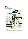
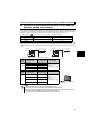
2.3.3 Terminal arrangement of the main circuit terminal, power supply and the motor wiring
zThree-phase 200V class
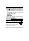
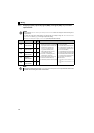
(1) Cable size and other specifications of the main circuit terminals and the earthing terminal
Select the recommended cable size to ensure that a voltage drop will be 2% or less.
If the wiring distance is long between the drive unit and motor, a main circuit cable voltage drop will cause the motor torque to
decrease especially at the output of a low speed.
The following table indicates a selection example for the wiring length of 20m.
Three-phase 200V class (when input power supply is 220V)
∗1 The cable size is that of the cable (HIV cable (600V class 2 vinyl-insulated cable) etc.) with continuous maximum permissible temperature of 75°C. Assumes
that the surrounding air temperature is 50°C or less and the wiring distance is 20m or less.
∗2 The recommended cable size is that of the cable (THHW cable) with continuous maximum permissible temperature of 75°C. Assumes that the surrounding
air temperature is 40°C or less and the wiring distance is 20m or less.
(Selection example for use mainly in the United States.)
∗3 The recommended cable size is that of the cable (PVC cable) with continuous maximum permissible temperature of 70°C. Assumes that the surrounding air
temperature is 40°C or less and the wiring distance is 20m or less.
(Selection example for use mainly in Europe.)
∗4 The terminal screw size indicates the terminal size for R/L1, S/L2, T/L3, U, V, W, PR, P/+, N/-, P1 and a screw for earthing (grounding).
The line voltage drop can be calculated by the following formula:
Line voltage drop [V]=
Use a larger diameter cable when the wiring distance is long or when it is desired to decrease the voltage drop (torque
reduction) in the low speed range.
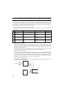
(2) Total wiring length
Connect a PM motor within the total wiring length of 30m.
Use one dedicated PM motor for one drive unit. Multiple PM motors cannot be connected to a drive unit.
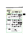
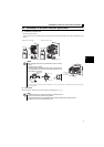
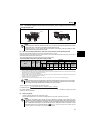
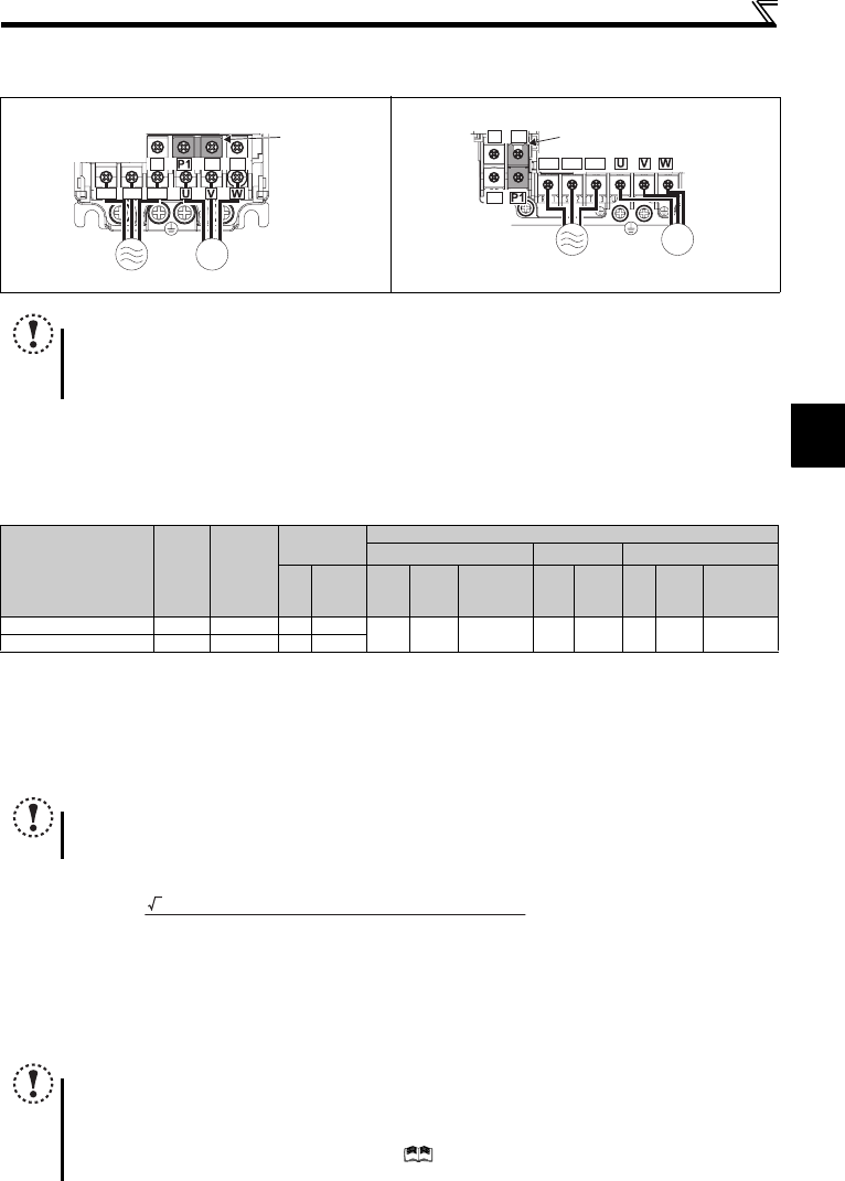
FR-D720-0.2K to 0.75K-G FR-D720-1.5K to 3.7K-G
NOTE
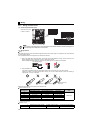
y Make sure the power cables are connected to the R/L1, S/L2, T/L3. (Phase need not be matched.) Never connect the
power cable to the U, V, W of the drive unit. Doing so will damage the drive unit.
y Connect the motor to U, V, W. Turning ON the forward rotation switch (signal) at this time rotates the motor
counterclockwise when viewed from the load shaft.
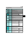
Applicable Drive unit
Model
Terminal
Screw
Size ∗4
Tightening
Torque
N
·
m
Crimping
Terminal
Cable Size
HIV Cables, etc. (mm
2
) ∗1
AWG ∗2
PVC Cables, etc. (mm
2
)
∗3
R/L1
S/L2
T/L3
U, V, W
R/L1
S/L2
T/L3
U, V, W
Earthing
(grounding)
cable
R/L1
S/L2
T/L3
U, V, W
R/L1
S/L2
T/L3
U, V, W
Earthing
(grounding)
cable
FR-D720-0.2K to 0.75K-G M3.5 1.2 2-3.5 2-3.5
2 2 2 14 14 2.5 2.5 2.5
FR-D720-1.5K, 3.7K-G M4 1.5 2-4 2-4
NOTE
y
Tighten the terminal screw to the specified torque. A screw that has been tightened too loosely can cause a short circuit or
malfunction. A screw that has been tightened too tightly can cause a short circuit or malfunction due to the unit breakage.
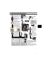
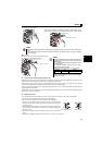
y Use crimping terminals with insulation sleeve to wire the power supply and motor.
NOTE
y Especially for long-distance wiring, the drive unit may be affected by a charging current caused by the stray
capacitances of the wiring, leading to a malfunction of the overcurrent protective function, fast response current limit
function, or stall prevention function or a malfunction or fault of the equipment connected on the drive unit output
side. If malfunction of fast-response current limit function occurs, disable this function. If malfunction of stall
prevention function occurs, increase the stall level. ( Refer to Pr. 22 Stall prevention operation level and Pr. 156 Stall
prevention operation selection in Chapter 4 of the Instruction Manual (Applied))
MotorPower supply
N/-
P/+ PR
IM
R/L1 S/L2 T/L3
Jumpe
r
Motor
Power supply
N/-
P/+
PR
IM
R/L1 S/L2 T/L3
Jumper
3 × wire resistance[mΩ/m] × wiring distance[m] × current[A]
1000