


Page 7
Revised 7/95 DFS-1 Manual
POWERTEC Ind. Corp.©
T1
T2
T3
1
2
3
4
5
6
7
8
9
10
Motor
+24V
Digital Out 1A
Digital Out 1B
Digital Out 2A
Digital Out 2B
Digital Out 3A
Digital Out 3B
Digital Out 4A
Digital Out 4B
FREQ REF OUT+
FREQ REF OUT-
FREQ REF COMMON
SPEED OUT
Speed Out COMMON
TB2
A
B
24V COMMON
Digital Input COMMON Cathodes
E-STOP
Digital In 1
Digital In 2
Digital In 3
Digital In 4
Digital In 5
Digital In 6
Digital In 7
FREQ REF IN+
FREQ IN-
FREQ REF SHIELD
+24V
DISPLAY POWER
DISPLAY +
DISPLAY-
Display COMMON
COMMUNICATIONS+
COMMUNICATIONS-
COMMUNICATIONS SHIELD
COMMUNICATIONS COMMON
Spacer
Spacer
TB3
A
B
Analog In COMMON
+10VDC
Analog In 1+
Analog In 1-
Analog In 2+
Analog In 2-
-10VREF
Analog Out 1+
Analog Out 2+
Analog Out COMMON
HALL SHIELD
HS1
HS3
HS2
HS4
HS5
HALL COMMON
HALL POWER
THERMAL
THERMAL POWER
TB1
A
B
Spacer
Spacer
1 2 3 4 5 6 7 8 9 10 11 12 13 14
1 2 3 4 5 6 7 8 9 10 11 12 13 14
1 2 3 4
1 2 3 4
1 2 3 4 5 6 7 8 9 10
1 2 3 4 5 6 7 8 9 10
Orange
Brown
Red
Blue
Yellow
Black
Green
Purple
White
Shield
POWERTEC
Brushless
DC Drive
DFS-1
Board
Analog
Speed Pot
1 2 3 4
Keypad
Display
Unit
Fwd Rev
RS-485
Communications
L3
L2
L1
G
T3
T2
T1
Stop
Run
E-Stop
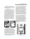
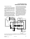
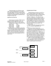
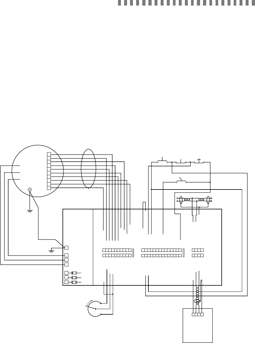
Figure 3: Basic connections to the DFS-1 controlled POWERTEC Brushless DC motor control, using the factory default
settings for some of the inputs and outputs. Note that the speed pot input is the default, and that using the 4-20mA input
will require a change in the DFS-1 setup.
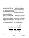
POWER CONNECTIONS:
POWERTEC Brushless DC motor controllers
are supplied with nominal input voltages of 230, 380,
and 460VAC. Three phase input power is required.
The input is not phase sensitive. Connect the appro-
priate power supply to the input fuses at L1, L2, and
L3 (check nameplate for proper input voltage and
capacity).
Connect the output terminals T1, T2, and T3 to
the respective terminals on the Brushless DC motor.
It is very important that the T1 terminal on the motor
connects to T1 on the drive, T2 of the motor connects
to T2 of the drive, and T3 of the motor connects to
T3 of the drive. An earth ground wire of the same
gauge as the motor power leads or one gauge smaller
(no smaller than #14 AWG) must be run from a bolt
1.0 CONNECTIONS
in the motor junction box to the ground terminal on
the drive. A wire must then be run from the ground
terminal on the drive (next to the motor terminals) to
an earth ground at or near the power source. The
Model 1000 drive does not have the common
circuitry connected to earth ground (chassis). In
most cases this works best, but in some cases it does
not. POWERTEC recommends connecting a short
jumper wire from the drive common at any one of the
several places available on the terminal strips to a
nearby point on the drive chassis or backpanel that
will establish this ground. This is more important in
applications where multiple drives are connected
together or serial communications from a host are
used. All other POWERTEC drives have the
common grounded by mounting screws on the
regulator boards.
KDU Cable is
Belden # 9463
“Blue Hose” or
equivalent