


Page 37
Revised 7/95 DFS-1 Manual
POWERTEC Ind. Corp.©
4.0 DFS - 1 SETUP
Making parameter changes requires the optional
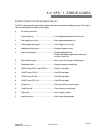
keypad display unit or a computer with serial
communications capability.
This section covers the basic steps necessary to
set up the DFS-1 beyond the needs of the default
parameters. The setup is arranged roughly from the
most basic and common steps to the least commonly
used parameter changes. You need only follow the
steps until you have all the parameters you will use
checked and/or changed.
The DFS-1 is shipped with a default set of
parameters which allows it to be connected as shown
in Figure 3 on page 3 and run with basic push-
buttons and a speed pot. This supplies a "baseline" of
operation which may be used to test the functionality
of the board.
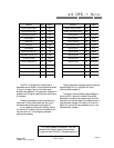
The above parameters are the most commonly
used ones. For other default settings, refer to the
parameter descriptions beginning on page 15.
If your needs are met by the list above, then all
you have to do is hook up the drive to power and to
the motor and run it. No changes in parameter
settings are necessary.
Parameter
No. Value
Parameter
No. Value
Maximum Motor Speed
6 1750
Master Jump Up Amount
49
1
High Engineering Units
14 1750
Master Jump Down Amount
50
1
Encoder Pulses Per Rev
7 120
Analog Input #1
17
0-10VDC
Pulse Multiplier
46 x4
Analog Output #1
25
Speed
PWM Mode
47
Non-Regen Analog Output #2
28
Load
Drive Gain
42 128
Input Debounce Value
53
10 mSec
Drive Stability
43 128
Digital Input #1
31
RUN
Motoring Current Limit
44 100
Digital Input #2
32
PRESET
Regenerative Current Limit
45 100
Digital Input #3
33
UP
Up/Down Function
48 Jump
Digital Input #4
34
DOWN
Float or Freeze Setpoint
54 Float
Digital Input #5
35
REVERSE
Mode of Operation
5 Master
Digital Output #1
38
RUN
Master Accel Rate
8 10k mSec
Digital Output #2
39
NO FAULT
Master Decel Rate
9 10k mSec
Digital Output #3
40
AT SPD
Master Preset Speed
12 200
Digital Output #4
41
REMOTE
For the purposes of this chapter, it will be
assumed that the setup is being accomplished
through the use of the KDU-1 keypad display unit.