


Page 19
Revised 7/95 DFS-1 Manual
POWERTEC Ind. Corp.©
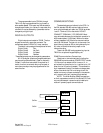
DFS-1 parameters are stored as DOUBLE
WORD values (32 bits), regardless of the actual size
of the data. This method is used to simplify the entire
system at a cost of a little extra data storage.
A double word consists of four BYTES (8 bits).
Each byte is a hexadecimal (base 16) value which
ranges from 00h (0 decimal) to FFh (255 decimal).
The largest number used in the DFS-1 parameters is
99,999 decimal, which, in hexadecimal notation is
0001 869Fh.
In many cases, information other than numbers
is passed and stored in the parameters. The left byte
is the most significant and the last byte is the least
significant. The arrangement of the bytes for this
purpose is: VL4 VL3 VL2 VL1 where VL4 is the
Most Significant Bit (MSB) and VL1 is the Least
Significant Bit (LSB). Each parameter breaks down
the bytes accordingly.
All four bytes are required in communications. A
number which must be either 0 or 1 must be passed
as either 0000 0000h or 0000 0001h.
1. UNIT ID
USE PARAMETER #1 TO IDENTIFY THE AD-
DRESS OF THE UNIT ON A NETWORK.
RANGE OF VALUES: 0000 0001h to 0000 00FFh
1 to 255 (decimal)
Default Value: 0000 0001h 1 (decimal)
The Unit ID number is installed in parameter #1.
This serves as an address on the external communica-
tions link. Two DFS-1 units cannot have the same
address while installed on the same communications
link.
There are 254 possible addresses if the default
value of 1 is not used as an address. Since the default
value is 1, there could be a problem if a new unit is
installed without changing the #1 parameter.
2. BAUD RATE
USE PARAMETER #2 TO SET THE COMMUNI-
CATIONS SPEED OF THE NETWORK.
RANGE OF VALUES: 0000 0000h to 0000 0007h
0 to 7 (decimal)
Default Value: 0000 0002h 2 (decimal)
This establishes the rate at which data is ex-
changed in the communications link. Every DFS-1 in
the communications link must have the same baud
rate set up in parameter #2. The parameter selects
from among eight industry standard baud rates:
NUMBER BAUD RATE
0000 0000h 38.4 Kilobaud (38,400 baud)
. . . . 01 19.2 Kilobaud (19,200 baud)
. . . . 02 9,600 baud
. . . . 03 4,800 baud
. . . . 04 2,400 baud
. . . . 05 1,200 baud
. . . . 06 600 baud
. . . . 07 300 baud
3. LOCAL / REMOTE CONTROL
USE PARAMETER #3 TO SET UP WHICH
FUNCTIONS ARE CONTROLLED REMOTELY.
RANGE OF VALUES: 0000 0000h to 0000 007Fh
0 to 127 (decimal)
Default Value: 0000 0000h 0 (decimal)
Parameter #3 is first broken down into bytes, and
then VL1 is further broken down into bits.
When broken down into bits, 00h = 0000 0000b,
and 7Fh = 0111 1111b.
VL4 is always 00h.
VL3 is always 00h.
VL2 is always 00h.
VL1 is broken down into eight bits, which are
numbered from right to left: 7654 3210h.
Functions are assigned as follows:
Bit Position Function
7 NOT USED
6 Master/Slave (not presently functional)
5 Frequency Mode
4 Reverse
3 Down
2Up
1 Preset
0 Run
A zero in a bit position means that function may
be controlled from an input terminal assigned to it. A
one in a bit position means that the function may
only be controlled via a communications link, such as
the operator’s station connection or the external RS-
485 communications link.
For instance, if VL1 is given a value of 01 (0000
3.0 DFS-1 PARAMETERS