


Page 15
Revised 7/95 DFS-1 Manual
POWERTEC Ind. Corp.©
5.0 Each of the two inputs may be set up one of
six ways:
1. -10 to +10 VDC
2. 0 to +10 VDC
3. 0 to 5 VDC
4. 1 to 5 VDC
5. 0 to 20 mADC
6. 4 to 20 mADC
6.0 Setup is by parameter selection (#18 for
Analog Input #1 and parameter #22 for Analog
Input #2).
7.0 Voltage inputs are a differential input connec-
tion.
8.0 Input impedance of each input in voltage input
mode is 200 Kilohms minimum.
9.0 Input impedance in milliamp input mode is
250 ohms.
Factory default setups are included so that the
DFS-1 does not have to be programmed prior to its
initial use. Factory defaults are only one of the many
ways the DFS-1 can be set up.
Default setups are as follows:
INPUT SETUP FUNCTION
1. 0 to +10VDC Speed Reference Input
2. -10 to +10VDC General Purpose Input
ANALOG OUTPUTS
1.0 There are two analog outputs on TB1:B.
2.0 The analog outputs may be programmed for
one of five modes:
2.1 Disabled
2.2 Motor Speed Output -10 to +10VDC
= 0 to 100% (Actual Motor Speed)
Default - Analog Output #1
2.3 Motor Load Output -10 to +10VDC
= 0 to 150%
Default - Analog Output #2
2.4 Set by Communications Link
2.5 Commanded Motor Speed
3.0 Output impedance is less than 100 ohms.
4.0 Maximum output voltage is +/- 10VDC.
5.0 Maximum current is 25mADC.
POWER SUPPLIES
+24VDC • Available at TB2:A14, and TB2:B1.
• The combination is fused at 250 milliamps
(mA). The fuse is self-healing.
• The opening of the fuse alerts the micro-
processor.
• These supplies should only be used for
push-buttons, relays, PLC outputs, etc.
which interface directly with the DFS-1.
They should not be used as general pur-
pose supplies.
+10VDC • Reference supply available at TB1:B2.
This output is rated at 100mA. This out-
put is current limited and thermally pro-
tected.
-10VDC • Reference supply available at TB1:B7.
This output is rated at 100mA, current
limited and thermally protected.
+5VDC • Supply for motor encoder available at
TB1:A9. This supply is fused at 100mA
with a self-healing fuse. When the fuse
opens, it alerts the microprocessor.
THIS SUPPLY IS FOR THE MOTOR ENCODER
ONLY!
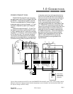
2.0 SPECIFICATIONS
ANALOG INPUTS
1.0 There are two analog inputs on TB1:B. (see
section 1.2, page 4)
2.0 Each input may be set up in one of several
modes.
3.0 Pre-programmed modes are:
3.1 General purpose Input
3.2 Speed Reference Input
3.3 Trim (dancer or load cell) Input
3.4 External Motoring Torque Limit
3.5 External Regenerative Torque Limit
3.6 Horsepower Mode
4.0 The mode of the input is set by parameter (#17
for Analog Input #1 and parameter #21 for
Analog Input #2).