


Page 55
Revised 7/95 DFS-1 Manual
POWERTEC Ind. Corp.©
Additional Info
DFS SOFTWARE MODIFICATION FOR
DYNAMIC BRAKING OR OUTPUT CONTACTOR
OPERATION
Functional Description
A new function for Contactor Aux has been added to the digital input choices. When configured as
described in the example, 24VDC must be present at this input for the drive to run. Parameter #62, Contactor
Delay, is a number of 25ms intervals that will occur between the DFS controller acceptance of a run command
and the firing of the transistors. If the Contactor Aux input signal is low, the DFS starts the timer and closes
the Contactor Output. If the Contactor Aux input does not switch high before the timer runs out, the drive will
return to the stop condition. If the Contactor Aux input does switch high, the drive will start running when the
timer runs out.
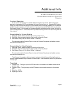
Example Setup for Dynamic Braking
1 Set Digital Input #7 mode to Contactor Aux, polarity to Active Low.
2 Set Digital Output #4 mode to Normally Open, polarity to Normally Closed.
3 Set Contactor Delay to 20 (20 x 25ms = 500ms = 1/2 second).
Run command causes the Contactor Output to close, the Contactor Relay opens, the feedback contacts
close and the drive starts to run.
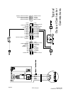
Example Setup for Output Contactor
1 Set Digital Input #7 mode to Contactor Aux, polarity to Active Low.
2 Set Digital Output #4 mode to Normally Open, polarity to Normally Closed.
3 Set Contactor Delay to 10 (10 x 25ms = 250ms = 1/4 second).
Run command causes the Contactor Output to close, the Contactor Relay closes, the feedback contacts
close and the drive starts to run.
The difference in the operation of the two types of contactors is that the Dynamic Braking Contactor is
normally closed whereas the Output Contactor is normally open. In both contactors, the auxilliary contacts are
normally open.
Terms Used
1 Contactor Aux - The digital input on the DFS board which is connected to the feedback contacts on the
contactor relay.
2 Contactor Output - The digital output on the DFS board which activates the solenoid on the contactor
relay.
3 Signal low - 0VDC
4 Signal high - 24VDC