


Page 47
Revised 7/95 DFS-1 Manual
POWERTEC Ind. Corp.©
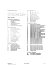
PARAMETER LIST:
Following is a list of the parameters used in
DFS-1. For a detailed description of each parameter
see the list in attachment B beginning on page 57.
Param# Description
COMMUNICATIONS SETUP
1 Unit Identification number
2 Baud Rate
3 Local/Remote
4 Communications Protocol
5 Mode of Operation
56 Communication Response Delay
BASIC DRIVE SETUP
6 Maximum Motor Speed
7 Encoder Pulses per Revolution
42 Drive Gain Setting
43 Drive Stability Setting
44 Motoring Current Limit
45 Regenerative Current Limit
46 Pulse Multiplier
47 Pulse Width Modulation Mode
48 Jump Or MOP Function
14 High Engineering units
53 Input Debounce Value
54 Freeze or Float Setpoint
59 EGU Tag Select
MASTER SETUP ONLY
12 Master Preset Speed
8 Master Acceleration Rate
9 Master Deceleration Rate
49 Master Jump Up Amount
50 Master Jump Down Amount
57 Master Jog Speed
60 Master Preset #2
SLAVE SETUP ONLY
10 Slave Acceleration Rate
11 Slave Deceleration Rate
13 Slave Preset Ratio
15 Base Ratio for Slave
16 Maximum Ratio for slave
51 Slave Jump Up Amount
52 Slave Jump Down Amount
55 Slave Minimum Ratio
58 Slave Jog Ratio
61 Slave Preset #2
INPUT/OUTPUT SETUP
17 Analog Input #1 Mode Select
18 Analog Input #1 Input Signal Conditioning
19 Analog Input #1 Low Engineering Units
20 Analog Input #1 High Engineering Units
21 Analog Input #2 Mode Select
22 Analog Input #2 Input Signal Conditioning
23 Analog Input #2 Low Engineering Units
24 Analog Input #2 High Engineering Units
25 Analog Output #1 Mode Select
26 Analog Output #1 Low Engineering Units
27 Analog Output #1 High Engineering Units
28 Analog Output #1 Mode Select
29 Analog Output #1 Low Engineering Units
30 Analog Output #1 High Engineering Units
31 Digital Input #1 Mode and Polarity
32 Digital Input #2 Mode and Polarity
33 Digital Input #3 Mode and Polarity
34 Digital Input #4 Mode and Polarity
35 Digital Input #5 Mode and Polarity
36 Digital Input #6 Mode and Polarity
37 Digital Input #7 Mode and Polarity
38 Digital Output #1 Mode and Polarity
39 Digital Output #2 Mode and Polarity
40 Digital Output #3 Mode and Polarity
41 Digital Output #4 Mode and Polarity
62 Contactor Delay
FUTURE EXPANSION
63 Future General use parameters
80-95 Future Special use parameters