


Page 9
Revised 7/95 DFS-1 Manual
POWERTEC Ind. Corp.©
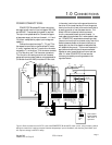
The default speed reference input is Analog
Input #1, located on TB1:B. The default input is for
a 0 to +10VDC for zero to full speed of the motor.
Terminal 3 is the positive side of the input and
terminal 4 is the negative side. If the speed signal
being used is externally supplied, the differential
input will have a noise cancelling effect. Terminal 1
on TB1:B is a common for shields.
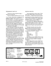
Reference sources of +10VDC and -10VDC are
supplied on the terminal strips at TB2:B2 and
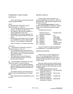
TB2:B7, respectively. The default speed pot connec-
tions should be made as illustrated in figure 3. Notice
that the (-) side of the differential input (terminal 4)
is connected by a jumper to common (terminal 1),
because the DFS-1 reference source is being used. If
an external reference source is to be used, no jumper
is necessary.
IN THE DEFAULT SETUP, ONLY ANALOG
INPUT #1 IS ACTIVE. WHILE THE OTHER
ANALOG INPUT HAS A DEFAULT SETUP, IT IS
NOT ACTIVE UNTIL THE USER CHANGES THE
SETUP TO MAKE IT ACTIVE.
The microprocessor will look ONLY to Analog
Input #1 for speed information until it is told to do
otherwise in the setup program.
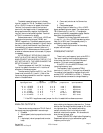
The other analog input to the DFS-1 is at TB1:B
(lower level) terminals 5 (+) and 6 (-). Both of the
inputs may be programmed for one of six inputs as
shown in the table below.
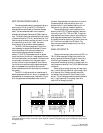
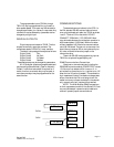
ANALOG OUTPUTS:
There are two analog outputs on TB1:B. Each of
the outputs may be programmed in several ways:
1. Disabled
2. Actual speed (value is proportional to motor
speed)
3. Load output (value is proportional to motor
load)
4. Comm set (value is set via Communica-
tions)
5. Commanded speed
Analog Output #1 default is a -10 to +10VDC
signal representing motor speed. The outputs are on
TB1:B terminals 8 (+) and 10 (-). The opposite
polarity is available by a parameter change. See the
description for parameters #26 and #27.
The default for Analog Output #2, terminals 9
(+) and 10 (-), is -10 to +10VDC representing motor
load, 0% to 150% load. The opposite polarity is
available by changing a parameter.
The maximum output current for the analog
outputs is 20 milliamps.
FREQUENCY INPUT:
There is only one frequency input on the DFS-1.
This input is used by the drive as the reference to
follow when the drive is in the SLAVE Mode of
operation. This input cannot be reassigned.
If the DFS-1 is in the MASTER mode, it will
ignore the frequency input.
The Frequency input is located at TB2:A
terminals 11(+) and 12 (-). This input is a differential
line receiver type intended to interface directly with
another DFS-1, a BCDMAX or CRM-1. There may
be multiple slaves connected to a single Master by
daisy-chaining the frequency reference line. The last
slave on the line should have the jumper at JP1 on the
two rightmost pins. This inserts a terminating
resistor at the end of the line to help eliminate
electrical noise from the system. All others should
be on the two leftmost pins.
Contact POWERTEC’s Application Engineering
Department before trying to use another type of
frequency on this input.
TB1:B TB1:B
Input Signal Level (+) input term (-) input term jumper terms input impedance
-10 to +10 VDC 3 or 5 4 or 6 none ** 200 Kohms
0 to +10 VDC 3 or 5 4 or 6 none ** 200 Kohms
0 to +5 VDC 3 or 5 4 or 6 none ** 200 Kohms
1 to +5 VDC 3 or 5 4 or 6 none ** 200 Kohms
0 to 20 mADC 3 or 5 1 4 or 6 to 1 250 ohms
4 to 20 mADC 3 or 5 1 4 or 6 to 1 250 ohms
** if the DFS-1 supplies are used, jumper 4 or 6 to 1 to establish the reference common.